• The move to the new server is done. There are some software and database maintenance updates in process. This has us passing the hat around to help out. We appreciate any donations. Seriously, even a dollar helps. The payment page may be found here - https://www.audiokarma.org/support.html

Reassembly Help for Thorens TD125 Mk ii

plresults

Active Member
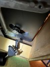
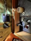
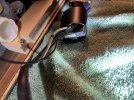
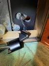
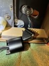
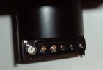
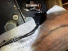
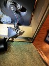
In my haste to get to & solder a broken arm wire, I didn't take pics of how the bits that sit below the arm connect to one another for this deck, and I am struggling.
In you have pics from your own reassembly process, or an explosion chart that would be wonderful. I didn't see anything from a Google search for same nor in here. Questions:
- where does the larger four wire connector sit - inside or out outside of the oval sleeve wire protector? Is it somehow attached to the metal bit with the serial number?
- where does the fifth wire from the arm connect. It is a black wire I assume is a ground. To the screws of the four wire connector, or to the long screws that hold the oval sleeve to the board?
- when joining the larger and smaller four pin connectors, how does the metal serial number figure into their assembly? What is orientation in space?
- the screws that held the two pin connectors together do not hold it together now - no threads to grab seemingly. Does one or both of those two screws get a bolt (which may have either been absent or lost)?

Pics of my 'situation' below. TIA my stereo fiend friends!
 

Attachments

  • IMG_7457.JPEG
    IMG_7457.JPEG
    155.2 KB · Views: 16
  • IMG_7458.JPEG
    IMG_7458.JPEG
    95.3 KB · Views: 16
  • IMG_7459.JPEG
    IMG_7459.JPEG
    164 KB · Views: 15
  • IMG_7460.JPEG
    IMG_7460.JPEG
    178.7 KB · Views: 15
  • IMG_7461.JPEG
    IMG_7461.JPEG
    153.4 KB · Views: 13
  • IMG_7462.JPEG
    IMG_7462.JPEG
    140.3 KB · Views: 16
Register to hide this ad
The SME tonearm, 3009, is the most documented tonearm on the www. Vinylengine has a pile of docs, ones that are what you are asking for if you are a member over there. If not, why don't you tell us, show us a picture of which SME tonearm you have and the answers will come pouring forth.

Of course, since the SME is the most documented tonearm on the web a picture search will also bring you proper photos of some of the issues you are seeking answers to.

3rd pic is wrong as are the 4th and 5th. The Delta plugs into the connector at the bottom of the tonearm. That connector is held to by the bolts for the screening can. Remove the phono cable and put is 10 feet away, DO NOT lose the bolt that holds the end of the delta as these are BA thread and not easy to find. You'll need it when you plug the phono cable back in later on.

Now work on just the tonearm, screening can, connector, serial number piece and those long bolts, the single black wire with a ring terminal on the end and assemble the bottom of the tonearm.

This first pic of the phono cable attached to the connector using the one bolt for that purpose. The other end has a friction fit to the ground lug on the connector.
3009 Wiring Connection Bolted End.jpg

This pic shows the other bolt holding the connector to the serial number plate going through the ground connection on that connector and the opening for the other bolt from the phono cable
3009 Wiring Connection.jpg

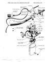
This diagram shows the screening can and the stuff associated with it. Note this shows the RCA jacks instead of the connector at the
base of the assembly, screening can put on last.
3009-R Parts Diagram.jpg

Screening can.jpg

On my tonearms the Ground Terminal Screw at the base of the screening can is very small as in the second diagram of the screening can assembly. The black wire ring terminal goes on one of the long bolts holding the connector to the bottom of the tonearm. The connector pins come out horizontally. After this is all assembled you can go get the phono cable and install it. You want it to allow free movement of your table inside the base for best result.

Post back how you are getting on.
 
Last edited:
It might be easier to remove the armboard from the table, three allen screws and it lifts off the table.
 
The SME tonearm, 3009, is the most documented tonearm on the www. Vinylengine has a pile of docs, ones that are what you are asking for if you are a member over there. If not, why don't you tell us, show us a picture of which SME tonearm you have and the answers will come pouring forth.

Of course, since the SME is the most documented tonearm on the web a picture search will also bring you proper photos of some of the issues you are seeking answers to.

3rd pic is wrong as are the 4th and 5th. The Delta plugs into the connector at the bottom of the tonearm. That connector is held to by the bolts for the screening can. Remove the phono cable and put is 10 feet away, DO NOT lose the bolt that holds the end of the delta as these are BA thread and not easy to find. You'll need it when you plug the phono cable back in later on.

Now work on just the tonearm, screening can, connector, serial number piece and those long bolts, the single black wire with a ring terminal on the end and assemble the bottom of the tonearm.

This first pic of the phono cable attached to the connector using the one bolt for that purpose. The other end has a friction fit to the ground lug on the connector.
View attachment 3290437

This pic shows the other bolt holding the connector to the serial number plate going through the ground connection on that connector and the opening for the other bolt from the phono cable
View attachment 3290438

This diagram shows the screening can and the stuff associated with it. Note this shows the RCA jacks instead of the connector at the
base of the assembly, screening can put on last.
View attachment 3290439

View attachment 3290445

On my tonearms the Ground Terminal Screw at the base of the screening can is very small as in the second diagram of the screening can assembly. The black wire ring terminal goes on one of the long bolts holding the connector to the bottom of the tonearm. The connector pins come out horizontally. After this is all assembled you can go get the phono cable and install it. You want it to allow free movement of your table inside the base for best result.

Post back how you are getting on.
Super helpful! I shall try to assemble again this evening. Yes mine is the 3009 arm.
 
Yes mine is the 3009 arm.
There is the 3009 Series I, 3009 Series II, 3009 Series II improved (removable or fixed headshell, different names for them), 3009 Series III,

The 125 II is too new to have a series I and probably a series II but the improved versions, yes. The under the armboard stuff is not from a series III.

So I was guessing you have a 3009 Series II Improved (fixed headshell) or the 3009/S2 Improved, the removable headshell model named that way because the headshell is part number S2. but you could have the earlier series II. How to tell and manuals for some of them:

 
There is the 3009 Series I, 3009 Series II, 3009 Series II improved (removable or fixed headshell, different names for them), 3009 Series III,

The 125 II is too new to have a series I and probably a series II but the improved versions, yes. The under the armboard stuff is not from a series III.

So I was guessing you have a 3009 Series II Improved (fixed headshell) or the 3009/S2 Improved, the removable headshell model named that way because the headshell is part number S2. but you could have the earlier series II. How to tell and manuals for some of them:

The head shell is removable, yes. Thank you!
 
Super helpful! I shall try to assemble again this evening. Yes mine is the 3009 arm.
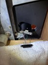
Blue: Thank you for your help again! Here us how I have it assembled now, which I believe matches the way it was when I started on it, and matches your directions, it appears. While not pictured, I have the small connector screwed to the shiny bracket and exiting horizontally as you directed. It seems now that I should have assembled the small wire connector to the oval shield & shiny metal bracket before screwing all to the bottom of arm with the long screws - so getting the screws to tighten the two pin connectors (large and small) the last few turns is going to be a bitch. I am going to test the table right now to see it my soldering fixed the no sound issue. I also note that this whole assembly is overly complicated! And more fragile & fussy than it should be! Further, there should be a hard fixture to isolate the wires under the plinth from any tugging that occurs with the outbound wires. Too delicate IMHO.
 

Attachments

  • IMG_7471.JPEG
    IMG_7471.JPEG
    97.4 KB · Views: 5
  • IMG_7472.JPEG
    IMG_7472.JPEG
    93.8 KB · Views: 5
  • IMG_7473.JPEG
    IMG_7473.JPEG
    93.8 KB · Views: 5
Blue: Thank you for your help again! Here us how I have it assembled now, which I believe matches the way it was when I started on it, and matches your directions, it appears. While not pictured, I have the small connector screwed to the shiny bracket and exiting horizontally as you directed. It seems now that I should have assembled the small wire connector to the oval shield & shiny metal bracket before screwing all to the bottom of arm with the long screws - so getting the screws to tighten the two pin connectors (large and small) the last few turns is going to be a bitch. I am going to test the table right now to see it my soldering fixed the no sound issue. I also note that this whole assembly is overly complicated! And more fragile & fussy than it should be! Further, there should be a hard fixture to isolate the wires under the plinth from any tugging that occurs with the outbound wires. Too delicate IMHO.
She sounds good! I just need to set up the stylus pressure & anti-skate properly. Thank you again!
 
We need to get the connector attached to the serial number piece as shown in the first two pictures. Those fine wires are not designed to take the stress of the phonon cable on them.

The connector you have pictured with the phono cable shows the bolt going the wrong way, connector>phono cable. It should hold the phono cable on the connector with the bolt head on the phono cable side.

There should be a second short screw to hold the other end of the connector to the serial number plate going in through the ground friction fit connection on the other end of the connector. I don’t see that bolt in your pics but it could be in the right place not bolted in or could be missing. You can see this bolt in my second picture. Maybe I do see it, also going the wrong way. It should go into the silver cup through the connector and attach the connector to the screening can system, probably screwed to the serial number plate.

I'm just going on memory and pics and diagrams but we need to fix the connector inside the screening can with all the wires tucked up in the can. As it is now, you might need to do more soldering sooner than you might want to when the blue wire pulls loose.

See part R. 1724 inthe diagram, the serial number plate holder? It shows two horizontal holes for the connector bolts. You can see those bolt holes in your pictures in the first post.
 
We need to get the connector attached to the serial number piece as shown in the first two pictures. Those fine wires are not designed to take the stress of the phonon cable on them.

The connector you have pictured with the phono cable shows the bolt going the wrong way, connector>phono cable. It should hold the phono cable on the connector with the bolt head on the phono cable side.

There should be a second short screw to hold the other end of the connector to the serial number plate going in through the ground friction fit connection on the other end of the connector. I don’t see that bolt in your pics but it could be in the right place not bolted in or could be missing. You can see this bolt in my second picture. Maybe I do see it, also going the wrong way. It should go into the silver cup through the connector and attach the connector to the screening can system, probably screwed to the serial number plate.

I'm just going on memory and pics and diagrams but we need to fix the connector inside the screening can with all the wires tucked up in the can. As it is now, you might need to do more soldering sooner than you might want to when the blue wire pulls loose.

See part R. 1724 inthe diagram, the serial number plate holder? It shows two horizontal holes for the connector bolts. You can see those bolt holes in your pictures in the first post.
I'll follow up more on Saturday. I did get the small wire connector screwed to the screening can bracket as you suggested (but I didn't take a photo). however the assembly is loose, which is probably what caused one of the wires to let go in the first place, necessitating the solder. I think if I disassemble and do it again in a better order, I can tighten it. I did connect the black wire out of the tone arm to one of the long screening can screws.
 
Back
Top Bottom