• The move to the new server is done. There are some software and database maintenance updates in process. This has us passing the hat around to help out. We appreciate any donations. Seriously, even a dollar helps. The payment page may be found here - https://www.audiokarma.org/support.html

Rebuilding a Pioneer SA-710-2 (FL) amp

Wombaton

Active Member
This one, to be precise! Trying to get back into the restoration game after a break with my first Pioneer project.
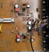
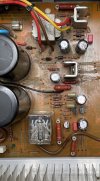
Currently in pieces, being cleaned:
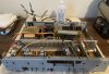
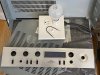
IMG_1821.jpg IMG_1825.jpg

I got it for almost nothing, as the seller thought it to be broken. But it is actually mostly functional.
Both channels play evenly in mono mode, with one channel cutting out when switched to stereo.
Me thinks, the mono / stereo switch must be dirty and here comes my first question:
how can I effectively clean these damn switches?
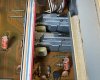
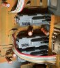
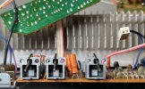
IMG_1822.jpg IMG_1823.jpg

These things look completely buttoned up, except for a very small opening where the lever is attached.
So, is it enough to blow in deoxit through that opening and work the level?
Or maybe I should drill a few more access holes somewhere?
Or should I desolder them from the board and open up from the bottom for real deep cleaning?
Would appreciate any sage advice.

THX,

Wmbtn
 
Register to hide this ad
tip: look to where the electrical contacts are connected to the pc board, that's the closest to the actual contacts
and getting the straw right at the crack is surprisingly effective in getting some in there.

The skilled restorers have developed the skills and confidence to (undamaged) desolder the switches,
open them up and clean them. NOT an easy, and a somewhat risky task.

Deoxiting is like plowing a line in a field.
Just a clean streak across a dirty expanse.
Moving the unit can jar the contact onto a dirty path, starting the need for deoxiting over again.
Shipping is TERRIBLE for that. So we had to step it up a notch.
 
Sorry for the delay with my response. Big THX to @markthefixer for the switch cleaning suggestions. Will try and then report back to this thread.
I did not realize that I could try approaching them from the bottom. Will have to see if I need to remove the front panel stay completely for that.
I definitely would not want to desolder and disassemble the switches unless absolutely necessary.
 
So, the highly anticipated update on the switch cleaning process. It was not possible to approach them from the bottom, but it is possible to approach from the front -- after removal of the inner face plate. This is how the switches look from this direction:

IMG_2402.jpg

IMG_2403.jpg

Sticking the spraying can straw into the front opening and pulling the trigger seemed to send most of the liquid into the switch (rather than cause blowback).

After cleaning all the switches and pots I reassembled the amp and tested it. The switches / pots operated silently (as expected), but interestingly enough the problem with channel dropout persisted and even became worse. Intrigued, I started testing the mono / stereo channel operation, while switching through all available inputs, except Phono. What I found was that a channel would drop and / or noise would happen on AUX and Tuner, while Tape 1 and Tape 2 would work perfectly with no noise or channel drops.

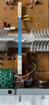
So obviously, the 'mono / stereo' switch did not seem to be the problem and instead I looked carefully at the input switch. That switch has a peculiar two-part assembly connected by some sort of a flexible 'bridge' (blue) that I have not dealt with before:

IMG_2494.jpg

I cleaned / lubed the part attached to the face place (bottom of the image) but did nothing to the other part. Now, looking at the face-plate part of the switch I saw that it is purely mechanical -- with an exception of a little circuit that lights up the input names (or 'function indicators' as the manual calls them) on the FL panel.

IMG_2496.jpg

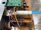
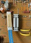
But apart from that, all this switch does is move the flexible flat metal piece inside the blue 'bridge' back and forth. So the whole thing works similar to a mechanical shutter release cable on a vintage camera. Apparently the electrical switching of the inputs happens within the other part of the switch. The connecting 'bridge' is easily detachable:

IMG_2495.jpg

After spraying contact cleaner through the slit on top of the switch, I reattached the 'bridge' and worked the switch back and forth as usual. This was indeed the precise area that needed to be cleaned -- now the amp works as it should on all inputs, with no noise of channel drops, and I can proceed with recapping it.

W.
 
I have a question while I am pulling the stuff together for the recap. I am thinking of potentially boosting the capacitance of the main power supply capacitors (originally 12000 uF) to 13000-15000 uF, depending on what I can find in stock with the usual suspects. However, I wonder: does anyone know if power switches on this series of amps are prone to arcing?

The power switch has a 0.01 uF / 250 VAC safety capacitor on it and there are two more of these (C85 @ 125 VAC and C78 @150 VAC) in the power supply. All seem to be class-X, if I am not mistaken. They all look reasonably modern (ceramic disk), but would it be prudent to replace them with new ones during a rebuild? If refreshing these caps, I forgot how to proceed: do I need to match the VAC on the schematic, or can I just replace all three with the same type that has the VAC > 250?

Or, for the power switch, should I do something better for arcing suppression, i.e., go for one of them CDE Quencharc caps (expensive) or roll out a triac mod? If arcing is not a problem, I'd be happy to leave the switch alone.

THX.
 
arcing is not a problem. if it isn't a problem after this long, it probably won't be in the future.

old caps were rated at + 80% so 15000 uf ok

keep original class-x caps.
 
Semiconductors

The nice thing about this amp is that, according to my impressions, none of its transistors are on the AK 'bad actors' list.

However, I usually try to refresh the diodes here and there. This amp is using 1S2076 in numerous places that are replaceable by 1N4148.

The diode bridge here utilizes 4x SR3AM-4, which seems to be well known to Pioneer restores. Naturally, I got a hold of this old AK thread that discusses replacements for this diode family.

Now, SA-710(FL) is rated for 65 W per channel (continuous) at 8 Ohm, and I was not able to find a rating for 4 Ohm, although I doubt that this amp is actually 'current unlimited.' So, if I do an estimate with 75-80 W at 4 Ohm, I end up with maximum forward continuous current of ~4.5 A for one channel and ~9 A for both channels.

Then, me thinks that SR3AM-4 and its generic 1N5404 (3A) replacement are a tad underrated for this.
I do like the -- already suggested -- 637-BY500-400 (5 A) fast recovery rectifier option quite a bit more, however, now there is also a 637-BY880-400 (8 A) option in the same package / case, as the 5 A one. It seems like the only major difference between the two is the slower recovery time for the latter: 1500 ns (same as for 1N5404) instead of 200 ns. Both of these options are ~$0.6 with 'buy 10' pricing at Mouser.

Therefore I wonder if 637-BY880-400 would be a good replacement for SR3AM-4, especially since it looks like 621-10A04-T has followed the dodo?
Of course, 8 A current is a hypothetical, since the main fuse on SA-710(FL) is 5 A.

THX,

Wmbtn
 
Last edited:
Wrapping up with semiconductors

I wonder if there is any general advice on what to do with diodes in a Pioneer amp of this age, i.e., circa 1980? I've done a few restorations before on amps that are at least 10 years older, and, e.g., Kenwood restorers for that period recommend replacing all diodes with modern analogs. Some of these, especially Zeners, tend to create noise as they age.

Then I also found this interesting thread, which suggests that original diodes could be left alone if things seem to be working properly. In my case, the amp is not making any strange noises and diode mounting locations (including Zeners) do not look 'cooked.' Therefore, I am inclined to let them be if nearby voltages are up to spec and unless anyone in this thread suggests that certain types need to be refreshed regardless.

Just to wrap up, here are the original diodes used (except for small 1S2076), as well their possible replacements:

OriginalReplacement
D13Zener 15V 0.5WMZ-150 (WZ-150)Protection Circuit15V, 0.5WCase: DO-35-2onsemi1N5245B
D15,D1610E2 (SIB01-02)Power Supply400V, 1A / 200V, 2ACase: DO-41 / DO-151N4004RLG / SBYV27-200-E3/54
D17-D20SR3AM-4Power Supply400V, 5A or 8ACase: D5.4x7.5DiotecBY500-400 / BY880-400
D21,D22Zener 33V 0.5WEQA01-33RPower Supply33V, 0.5WCase: DO-35-2VishayBZX55B33-TR (?)
D23Zener 19.2V 0.5WMZ-192 (WZ-192)Power Supply19.0V, 0.5WCase: DO-35-2no exact replacement, but a 19V one should doonsemi 1N5249BTR (?)

Here, I am not bumping up the original power dissipation ratings on Zeners.
Any comments on the sanity of replacement choices are welcome.

In general, I keep my BOM and accompanying comments in an Excel sheet, which I can share upon request.
 
Some amplifier porn as the recapping process continues:

(1) Eq Amp area:

IMG_2510.jpg

(2) Power supply / protection area:

IMG_2509.jpg

Electrolytic capacitors up to (and including) 4.7 uF are being replaced by Wima film (red boxes). Resistors of 1/2 W and higher are being bumped up in the power dissipation rating. Any semiconductor components staying as they are for now. Cleaning up the gooey mess as I move along. So far, everything from my part list fits really well, even on 'crowded' locations, with no capacitors hanging above the board. And of course, I just found out that I'd forgotten to get a replacement for R112.
 
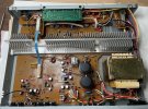
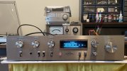
Finished, rebuilt and working like a champ:

IMG_2571.jpg


IMG_2572.jpg


IMG_2576.jpg

Diode bridge rebuilt with beefy Diotec BY880-400 devices, the rest of the diodes including Zeners left unmolested. I was also not able to get anything cool as a replacement for the 12000 uF filter caps that would fit in place perfectly. Had to go with 13000 uF / 63V 'snap in' Kemets, i.e., a very modest capacity boost. Removing all the glue around these capacitors was a pain.

After being done with all replacements, I checked idle current per instructions, i.e., Sec. 8.1 on p. 10 in the service manual. That is one hazy description that actually does NOT provide the desired value (or interval) for the idle current. It only says: if the voltage is less than 4.4 mV,
cut some jumper wire. Apparently, this wire is the only means of controlling the current. Anyway, the idle current turned out to be in decent shape, or so I would guess in the absence of any more specific information: 19 mV / 24 mV in L / R channels (rather symmetric!), so no need to cut any jumpers.

Finally, I also did the standard DC-offset check. 20 mV on the Left (not bad!) vs 70 mV on the right (meh). Same as for the idle current, this amp does NOT provide any way of adjusting the offset. I would really like to bring the DC voltage down on the Right, but since I do not really understand the amp schematics in any reasonable detail, not sure what I can do here. If any of the more experienced members of the forum have any ideas, I'd be most grateful.

W.
 
Back
Top Bottom