• The move to the new server is done. There are some software and database maintenance updates in process. This has us passing the hat around to help out. We appreciate any donations. Seriously, even a dollar helps. The payment page may be found here - https://www.audiokarma.org/support.html

Rebuilding an electrolytic capacitor... revisited

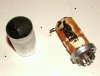
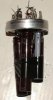
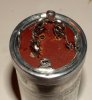
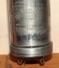
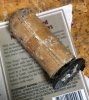
Here's how those old caps are constructed, and how they look. The shiny aluminum layer is the ground, and goes all the way through the roll. The thicker, grey colored layer is the etched aluminum positive side of the cap. This is a 4 section cap 20 Mfd x 500V. Each one of the sections follows the other in order on the roll, with a gap between them. On this particular cap, 2 of the sections tested good, one had some leakage, and the last one had high leakage. I wish I had kept track of them as I took it apart, but I didn't. However, I suspect that the outer most cap on the roll is the one that failed. If you look at the color of the insulating paper, the first section to be unrolled is lighter and spotted. As I get deeper into the roll, the paper color gets more consistent, and wetter. It is likely that the drier paper was the leaking cap.
You can also see how the lead is brought out of the roll, just a spot welded tab on the sheet.
I also noticed that a 40 Mfd x 500V cap I took apart to harvest the ground ring off of has only 2 sections. I suspect that if I unrolled it I would find the positive foil to be twice as long, and hence take up twice as much room, meaning 4x40 would not have fit in the can. Seems obvious once I see how these are made up.
 

Attachments

  • IMG_1601.jpg
    IMG_1601.jpg
    65.5 KB · Views: 76
  • IMG_1614.JPG
    IMG_1614.JPG
    112.5 KB · Views: 73
  • IMG_1615.JPG
    IMG_1615.JPG
    136 KB · Views: 72
  • IMG_1617.JPG
    IMG_1617.JPG
    120.4 KB · Views: 71
  • IMG_1616.JPG
    IMG_1616.JPG
    67 KB · Views: 73
Great pictures, thanks for contributing to the thread. I have unrolled many capacitors but never took any pictures. This will help a lot.
 
I'm still wanting to do replace the Can Cap in my Dynaco FM-3 with film caps that I have already ordered. I was going to do the Can cap new cap install as well but I just want to go in another direction. I'm thinking out a way to mount them in the existing area around the where the Can cap goes but make it look nice and not a hack job. I do have the PEC upgrade the Power supply PCB fully stuffed with the Electrolytic caps I put in from ESL. The PEC upgrade was a huge improvement in sound along with the Dynamicaps in the output stage with Takman resistors. Once I get the film caps in the power supply installed this really should be one very nice sounding tuner.
 
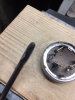
After re-stuffing about 5-6 cans I got tired of shish kebabing myself and made a jig. 1-3/8" wood bit makes a perfect hole to fit can in it and clamp it in the vise.
Also, rounded corner flat blade screwdriver helps lifting the crimp edge without damage. Working on crimp straitening pliers next.

upload_2020-7-4_20-57-59.png

upload_2020-7-4_20-58-37.png
 
I have a different technique. I've captioned the photos with the steps, in order.
 

Attachments

  • Step 1 Tube Cutter.JPG
    Step 1 Tube Cutter.JPG
    70.8 KB · Views: 41
  • Step 2 Cut at Seam.JPG
    Step 2 Cut at Seam.JPG
    110.2 KB · Views: 40
  • Step 3 Cap Disassembly.JPG
    Step 3 Cap Disassembly.JPG
    85.6 KB · Views: 41
  • Step 4 Isolate Base.JPG
    Step 4 Isolate Base.JPG
    86.5 KB · Views: 41
  • Step 5 Cap Components.JPG
    Step 5 Cap Components.JPG
    95.8 KB · Views: 39
  • Step 6 Drill Holes.JPG
    Step 6 Drill Holes.JPG
    186.4 KB · Views: 39
  • Step 7 Assembly Part 1.jpg
    Step 7 Assembly Part 1.jpg
    79.5 KB · Views: 40
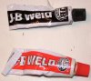
  • Step 8 JB Weld.JPG
    Step 8 JB Weld.JPG
    115.6 KB · Views: 39
  • Step 9 Mixing Epoxy.JPG
    Step 9 Mixing Epoxy.JPG
    135.7 KB · Views: 39
  • Step 10 Clamping Assembly.JPG
    Step 10 Clamping Assembly.JPG
    109.3 KB · Views: 40
Here are the remaining pics.

One "benefit' of this technique is that you can "mix and match" cans with different bases. E.g. If you need a short can with 4 terminals, they will all be close enough to fit. And if the result isn't like what's stamped onto the can, you can make a label for it.
 

Attachments

  • Step 11 Wiring Terminals.JPG
    Step 11 Wiring Terminals.JPG
    136.1 KB · Views: 36
  • Step 12  Seam Closeup.JPG
    Step 12 Seam Closeup.JPG
    175 KB · Views: 38
  • Mix n Match.jpg
    Mix n Match.jpg
    117.2 KB · Views: 37
  • Cap Label.jpg
    Cap Label.jpg
    90.2 KB · Views: 37
I'd like to thank you all for this thread.
I'm still a lazy guy and use CE, Authenticcap, or Hayseed but at least I have a recipe.
 
Looks nice Jon. The epoxy is only in the joint between base and cylinder, right? This can be a problem if amp is not carefully positioned for service. Too easy to bump. Can caps are usually tallest components. I get carried away and can easily see myself breaking the cylinder off.

I would still prefer to open the crimp so tar and phenolic washers can be washed out of old electrolyte. I hate that smell and I think remnants of old electrolyte could potentially damage new capacitor leads.
 
Looks nice Jon. The epoxy is only in the joint between base and cylinder, right? This can be a problem if amp is not carefully positioned for service. Too easy to bump. Can caps are usually tallest components. I get carried away and can easily see myself breaking the cylinder off.

I would still prefer to open the crimp so tar and phenolic washers can be washed out of old electrolyte. I hate that smell and I think remnants of old electrolyte could potentially damage new capacitor leads.

Yes, nice job for sure. But I too still prefer to open up the can. One reason is that I have a supply of NOS can capacitors so I can harvest a new phenolic washer and get a new, never crimped steel mounting ring. Knowing that, I am not too careful when removing the old can.
 
I've only done the can on my Sherwood 5500. Used a utility knife with a new blade and cut the can off about 1/4" up from the base and used a strip of aluminum HVAC tape to attach the can back together. You would not notice it had been tampered with if you weren't looking closely.
Using the crimp method would be stronger if that is a consideration. I like Grindfix's plywood fixture.
 
It's just a block of 2 x 4 pine stud. Soft enough that it gently flexes when clamped in the vise and keeps can steady without movement. Hole needs to be cleaned up with file to male sure wood grain structure is not leaving imprint on the can, but then this may be actually desirable in some designs??
 
Looks nice Jon. The epoxy is only in the joint between base and cylinder, right? This can be a problem if amp is not carefully positioned for service. Too easy to bump. Can caps are usually tallest components. I get carried away and can easily see myself breaking the cylinder off.

Actually, I use a big glob of epoxy -- enough so when the can is turned upright, it would probably be about 1/4" thick on the bottom. What you see of the seam is only what's leaked out around it.

The wires that run through the bottom to the capacitors inside act like reinforcing rods for the epoxy. I haven't tried breaking one open, but I'm sure a bump ain't gonna do it. The fact that it probably can't be reopened might be a drawback for some. Get it right or toss it . . .
 
Back
Top Bottom