• The move to the new server is done. There are some software and database maintenance updates in process. This has us passing the hat around to help out. We appreciate any donations. Seriously, even a dollar helps. The payment page may be found here - https://www.audiokarma.org/support.html

Recap of SX-950 Equalizer Amp AWF-011

Kim Beneteau

New Member
Hi new here. Just starting out on a recap of a SX-950 Equalizer Amp AWF-011. Having difficulty locating replacement caps 647-UKL1H010KDDANA 1uF 50v (C1 & C2) neither Mouser or Digi-Key have it in stock and not sure what part might be an equivalent replacement?
 
Register to hide this ad
I'm debating on whether to take a dive on a oscilloscope. I haven't used one but can figure it out. There's a RIGOL DS1202 Z E that I can pick up for around $250....any thoughts?
 
Went with the scope and learning as I go. Decided to start on the Flat Amp Board AWG-038 first, followed by the Switch Assembly Board AWS-094. So far so good, everything checks out and already seeing what I believe is a reduced noise signal as a result. An interesting discovery afterwards, the volume control would previously appear to reach max within 15-20% of 0, now the volume scales smoothly across the full range from 0 to 100. Next up is the Tone Amp Board AWG-039.
 
Last edited:
Question: on Tone Amp Board AWG-039. I noted that C29 and C30 were jumped, I bought this receiver new, anyone run into this before? I'm going to go ahead and put the 10uf 25v caps in I'm pretty sure they're not going to hurt anything.
 
They are superfluous, the only possible source of input for the tone amp is the output of the flat amp with it's own 4.7uF output coupling cap.
 
Finally got to the AWF-011 board. Determined that I have a "B" board and installed the two additional caps per the list. After completion, connected a turntable and no sound when connected through phono 1 or phono 2 (it was giving me problems prior to installing the caps/trans). Good input signal on both channels. Measured +28v at pin 6 which checks but measured -50.6v at pin 2, should be -19v. Planning on doing the power supply next and assume the problem could be there. Would prefer to identify the specific problem and fix that in the PS before I go willy nilly replacing everything on the PS board. Any thoughts on where to look?
 
specific problem? -50.6 at the -19v output. There's plenty of AWR-101 PSU write ups on here that cover it. sigh... one more time....

R18 (24k) & R17 (15k) form a voltage divider that takes pin 14's -51.5v and gives out -19.8 volts.
C23 is added on for several reasons. Stability, ramping up gently...
R19 (150 ohms ) is a bit superfluous, 0.9v drop (-51.5 - -50.6) says 6 mA load. It's a 1/4 watt resistor, so maybe it's supposed to pop on a fault.The transistor will pop sooner. Sometimes it's supposed to share the heat of reducing the voltage, instead of the transistor handling all the heat.

The workhorse is Q6 2sa720. the emitter will follow the base voltage MINUS the (about) 0.6v Vbe, so the C23 voltage of -19.8 applied to the
base of Q6 will give -19.1v at the emitter (pin 15)
-50.6v says Q6 is shorted.

replacement is usually a ksa1220, but you can TEMPORARILY get away with using ksa992 as it's dissipating 0.19w and the a992 can handle 0.5w max.
ksa1220 is being discontinued, so TTA-004B (757-TTA004BQ @ $0.48) is fine.

Re: power supply. my rant:
all new electrolytics, they have been cooking and working hard for years.
ditto for semiconductors, BOTH transistors AND diodes!! They have worked hard and heated up for years.
And all are made with older processes and materials - we have learned a lot in the intervening decades.

power supply #1
protection #2
power amps #3

why? when those three things are done the issues that remain are NOT destructive.. may SOUND horrible, but no blowups...

The first time you dither around, and in the meantime a bad trimmer or a 2sc1451 cause the amp to erupt in smoke and flames, You'll change your priorities.
AND there CAN be 2sc1451 IN THE SX-950!! Amp transistors Q7 & Q8 are listed at 2sc1628 but the BOM admits that 2sc1451's could be used.

 
Last edited:
specific problem? -50.6 at the -19v output. There's plenty of AWR-101 PSU write ups on here that cover it. sigh... one more time....

R18 (24k) & R17 (15k) form a voltage divider that takes pin 14's -51.5v and gives out -19.8 volts.
C23 is added on for several reasons. Stability, ramping up gently...
R19 (150 ohms ) is a bit superfluous, 0.9v drop (-51.5 - -50.6) says 6 mA load. It's a 1/4 watt resistor, so maybe it's supposed to pop on a fault.The transistor will pop sooner. Sometimes it's supposed to share the heat of reducing the voltage, instead of the transistor handling all the heat.

The workhorse is Q6 2sa720. the emitter will follow the base voltage MINUS the (about) 0.6v Vbe, so the C23 voltage of -19.8 applied to the
base of Q6 will give -19.1v at the emitter (pin 15)
-50.6v says Q6 is shorted.

replacement is usually a ksa1220, but you can TEMPORARILY get away with using ksa992 as it's dissipating 0.19w and the a992 can handle 0.5w max.
ksa1220 is being discontinued, so TTA-004B (757-TTA004BQ @ $0.48) is fine.

Re: power supply. my rant:
all new electrolytics, they have been cooking and working hard for years.
ditto for semiconductors, BOTH transistors AND diodes!! They have worked hard and heated up for years.
And all are made with older processes and materials - we have learned a lot in the intervening decades.

power supply #1
protection #2
power amps #3

why? when those three things are done the issues that remain are NOT destructive.. may SOUND horrible, but no blowups...

The first time you dither around, and in the meantime a bad trimmer or a 2sc1451 cause the amp to erupt in smoke and flames, You'll change your priorities.
AND there CAN be 2sc1451 IN THE SX-950!! Amp transistors Q7 & Q8 are listed at 2sc1628 but the BOM admits that 2sc1451's could be used.
Ouch!...thoroughly chastened.

Thank you for your concise explanation of that section of the circuit, it confirmed my suspicion that it was at or around Q6, I was trying to test Q6 in circuit with a multimeter to see if I could tell but still not up to speed on that process. Will go back and try again. The BOM I'm using calls for Q6 replacement in AWR-101 as 512-KSA1013YBU will that work?

By getting the voltage back to -19.1v at the AWR-101 board do you think the lack of output signal at that board resolve itself?

your rant makes sense :-)

Don't quite understand that last paragraph but smoke and flames are bad ju ju and not where I want to be!

Can't tell you how much I appreciate your advice/guidance. Thank you.
 
yes, ksa1013 for Q6.
fixing -19 gets sound? unlikely. The a992 and c1845's MAY have survived the extra 30 volts over the -19, but I wouldn't count on it.
testing ANY transistor should be done out of circuit, some faults like short circuits can be found by ohms testing with a DMM, but even at best OUT of circuit it can only say "not any of THESE faults, but I can't say it's good".

last paragraph says that 2sc1451's COULD be found in YOUR power amplifiers, at Q7 & Q8, and it would be a good idea to NOT power things up until you KNOW that it either isn't in there, or it was and you replaced it.

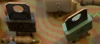
The bad 2sc1451's look like this:
upload_2022-12-27_22-8-39.png

Instead, if they look like these square ones, you dodged a bullet.
upload_2022-12-27_22-11-8.png
 
Last edited:
Looks like a dodged a bullet but got caught by shrapnel :). Went through AWR-101, powered up, has sound....good. Noticed the speaker and Phono-Aux lights not on as selected, however, have a stereo signal light when tuned to station? Checked voltage at pin 2 & 3 and 0v. Voltages check for all other pins. Collector voltage for Q8 is 26.85, voltage on both sides of R20 is same at 26.85, base voltage at Q10 is 6.84, emitter voltage at Q10 is -.86. I'm thinking R20 is bad, reading 98.6 ohms if I'm reading it correctly?
 
Last edited:
Looks like a dodged a bullet but got caught by shrapnel :). Went through AWR-101, powered up, has sound....good. Noticed the speaker and Phono-Aux lights not on as selected, however, have a stereo signal light when tuned to station? Checked voltage at pin 2 & 3 and 0v. Voltages check for all other pins. Collector voltage for Q8 is 26.85, voltage on both sides of R20 is same at 26.85, base voltage at Q10 is 6.84, emitter voltage at Q10 is -.86. I'm thinking R20 is bad, reading 98.6 ohms if I'm reading it correctly?

Voltage is the same on both sides of R20 because no current is being drawn though it. Not the problem.
Q10 base voltage of 6.84,yet emitter voltage of -.86 (actually NOT at 6v at emitter means bad) says Q10 is open / bad
Q9 could be good, or open, it's not shorted but somehow Q10 got hurt.
Usually we treat such configurations as a single and replace them both.
 
Voltage is the same on both sides of R20 because no current is being drawn though it. Not the problem.
Q10 base voltage of 6.84,yet emitter voltage of -.86 (actually NOT at 6v at emitter means bad) says Q10 is open / bad
Q9 could be good, or open, it's not shorted but somehow Q10 got hurt.
Usually we treat such configurations as a single and replace them both.
Thank you, your response made me think....I pulled Q10 to replace it and took another look at the data sheet and the pin placement vs the service manual. Found my rooky mistake....had installed it wrong. Reinstalled correctly and bingo, working properly! Went back to the Equalizer Amp board and found the same problem and fixed that as well. Then went and checked all the other transistors I installed...thankfully the rest were correctly installed. On to the Power Amp Board AWH-059 but not till next week. Waiting on some supplies.
 
Just a status update because this thread became a defacto rebuild of my SX-950 and a huge learning curve. First I want to say thanks to markthefixer for keeping me on the straight and narrow! I also want to say thanks to everyone who contributes to this forum, such an incredible wealth of information and lastly thanks to all those who contribute relevant content to YouTube in particular, maxxarcade, navydiving, xraytonyb and many others I gleaned information from.

As far as the SX-950, after a holiday break I finished the Power Amp Board AWH-59 and made appropriate adjustments. That makes it complete using the BOM found on this platform. I stayed away from the Tuner board, it's working and I don't have the tools to make adjustments. I didn't replace the two big caps. I have to look into what it's going to take to measure their specs and whether they need changing. The unit sounds fantastic! In the meantime I found a new project to tackle....a RT-707 Reel to Reel that needs some love. I'll start a different thread for that.
 
Back
Top Bottom