• The move to the new server is done. There are some software and database maintenance updates in process. This has us passing the hat around to help out. We appreciate any donations. Seriously, even a dollar helps. The payment page may be found here - https://www.audiokarma.org/support.html

Recently bought a L-07C

ampman

AK Subscriber
Subscriber
Hello everyone,
Recently acquired a L-07C in basic cosmetic condition. Before diving into repairing it, what should one look at while inside?

Is there a paint match for the factory color?

I plan to add this to a system with the L-07T and L-5M. Hoping it is great.

Thanks in advance.
 
Register to hide this ad
There’s good info on this thread:

 
@Kingbleu thread is very good.

I have a few notes in the resto sticky.

If it works, I'd probably leave it alone. Mine had a few problems but these sound great once working.

Post your plans and you should get some advice
 
Thanks for the information. Appreciate the help.

My plan is to restore the L-07C as close to factory specs as possible. Not a total replacement of all components but replace the electrolytic caps as a start. Clean the switches and inspect the solder for cold joints. All the typical checks and all.

Definitely want all the help I can get.

Mine has a problem. Maybe more than one.

I have the L-07C on my bench and started baseline testing. Input a signal and measure the output.

-Input a 140mV analog signal across 20Hz to 20kHz sweep into the AUX and Tuner inputs.
AUX Input:
--Both channels show output:
---left channel is definitely low.
---Right channel is basically okay.
Tuner Input:
--Both channels show output:
---left channel is definitely low.
---Right channel is basically okay.

Phono 1 Input:
Input a 2.0mV analog signal from 20Hz to 20kHz sweep into the Phono 1 inputs.
--Both channels show output:
---left channel is 8.306v to 97.37mV.
---Right channel is 8.293 to 96.73mV

Phono 2 Input:
Input a 0.20mV analog signal from 20Hz to 20kHz sweep into the Phono 2 inputs.
--Both channels show output:
---left channel is 19V to 483.7 mV.
---Right channel is 18.8V to 481.2 mV.

Both phono inputs follow an odd curve.

-Checked the power supply B+ & B- voltages.
--B+ is ~+61.0VDC
--B- is ~-60.1VDC

That as far as I've tested.

Thanks in advance.
 
When measuring the Phono inputs, did you compensate the RIAA curve? From the voltages you measured, I guess not.
In the specs of the L07C, with an input of 2mV at 1KHz on the Phono 1 (MM), you should get 1 Vout, measured at the Line out terminals, with the Volume at max.
For phono 2 (MC), 0.2mV to get 1 Vout, at 1KHz.
 
Thanks for the information. Appreciate the help.

My plan is to restore the L-07C as close to factory specs as possible. Not a total replacement of all components but replace the electrolytic caps as a start.

Definitely want all the help I can get.

Mine has a problem. Maybe more than one..

I think these are difficult to work on. I'd suggest to replace a few caps that are easy to get a feel of the difficulty. This is not like a typical resto.
 
When measuring the Phono inputs, did you compensate the RIAA curve? From the voltages you measured, I guess not.
In the specs of the L07C, with an input of 2mV at 1KHz on the Phono 1 (MM), you should get 1 Vout, measured at the Line out terminals, with the Volume at max.
For phono 2 (MC), 0.2mV to get 1 Vout, at 1KHz.
Thanks for the advice. I did use a preset curve. One of the preset RIAA curves in the AP System 1. I repeated the test a couple times sweeping from 20 to 20kHz.
I did not see what I expected from any input/output.
I’ve restored a few pieces, including pioneer reel-to-reel decks. Is this more involved than that?
 
I did use a preset curve. One of the preset RIAA curves in the AP System 1. I repeated the test a couple times sweeping from 20 to 20kHz.
I did not see what I expected from any input/output.

It sounds like the RIAA compensation is performed on the capture side, not the generator side of the AP Sys1.

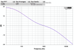
I think you'll find it's a setup issue with the AP as those numbers suggest no RIAA compensation is being applied on the gen side. ie you are seeing essentially something like this (no correction curve applied to the captured results):

1792829079179.png
 
Hello,
Thanks for the help.

Here is the setup for the AP Sys1:
1792855167819.png
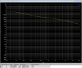
I am using the AP RIAA_Pre EQ curve in the generator. This is the resultant curve.
1792855266633.png
FWIW - the AP Sys1 passes the selftests.

What are your thoughts?
 
Forgot a couple specs. The prior AP Sys1 setup and curves are for Phone 2(MC). Output-on. Subsonic filter is off. Gain (both channels) is -15dB. Bass & Treble set to flat. Master Volume is '0' (MAX). Tape is REC OFF.


Switched to Phono1(MM). The following is the AP Sys1 setup and curves for Phono 1(MM). Output-on. Subsonic filter is off. Gain (both channels) is -15dB. Bass & Treble set to flat. Master Volume is '0' (MAX). Tape is REC OFF. Using the same RIAA-PRE curve.

1792856434440.png

1792856434445.png
 
It sounds like the RIAA compensation is performed on the capture side, not the generator side of the AP Sys1.

I think you'll find it's a setup issue with the AP as those numbers suggest no RIAA compensation is being applied on the gen side. ie you are seeing essentially something like this (no correction curve applied to the captured results):

View attachment 3862502
Your advice is spot on. I did not choose the proper Waveform. Once that was corrected the Phono1 & Phono2 inputs operated as expected.
Virtually flat response from both inputs.

Thanks for helping me. Appreciate it.
 
Last edited:
You have 40dB (100x) between 20Hz and 20kHz (+/-20dB) pivoted around 1kHz.

You can correct for the RIAA curve in either the gen itself or after the capture with a compensation file (as is done with my QA403). Arguments can be made for both approaches.

I think you'll find the L-07c is pretty good on phono deviation except in the absolute lowest octaves. IIRC it has DC offest trimmers that might need attention (or was that the L-07cII?) Also, take the signal from the tape outs (for phono stage tests)- not the line outs or you are also adding the entire preamp to the phono stage results.
 
I also would suggest not fixing what isn't broken. I have one of these too that I bought as-is / for parts, though it was in excellent condition. One of the relays wouldn't close on start up, and I only had to troubleshoot the PSU to get it working again. But even though I only desoldered (very carefully!) a few components, I could tell that all the traces were on the verge of letting loose. Since it's a double sided PCB, some components are soldered on both sides, and I don't think there are (reliable) conductive vias, so many components need to be desoldered from both sides. The risk of pads coming off is too high, so I've decided to live with mine as-is. I had one pad come off and managed to get it stuck down again with JB weld high heat epoxy, but I've decided to not go any further with it unless something else is actually broken.
 
Back
Top Bottom