• The move to the new server is done. There are some software and database maintenance updates in process. This has us passing the hat around to help out. We appreciate any donations. Seriously, even a dollar helps. The payment page may be found here - https://www.audiokarma.org/support.html

Rectilinear crossover help

Mark_L

New Member
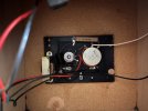
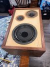
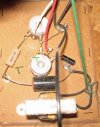
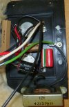
Novice here, looking to check out this crossover to see if it needs to be recapped. Speakers are Rectilinear Mini III’s. I’m unsure how to proceed. The crossover is glued to the cabinet, so it looks like all the work has to be done like it is. Any advice is welcome, as well as advice on which parts I need and where to source them. Thanks.
 

Attachments

  • IMG_2229.jpeg
    IMG_2229.jpeg
    169.1 KB · Views: 32
  • IMG_2228.jpeg
    IMG_2228.jpeg
    97.5 KB · Views: 34
  • IMG_2225.jpeg
    IMG_2225.jpeg
    152.1 KB · Views: 34
Register to hide this ad
Definately replace the two black caps with the red ends. They are ka ka. The larger can be replaced by a Mundorf electrolytic of the same value. It may be necessary to use a film cap in parallel if you can't find the exact equivalent. Replace the smaller cap with a film cap like this from Parts Express.

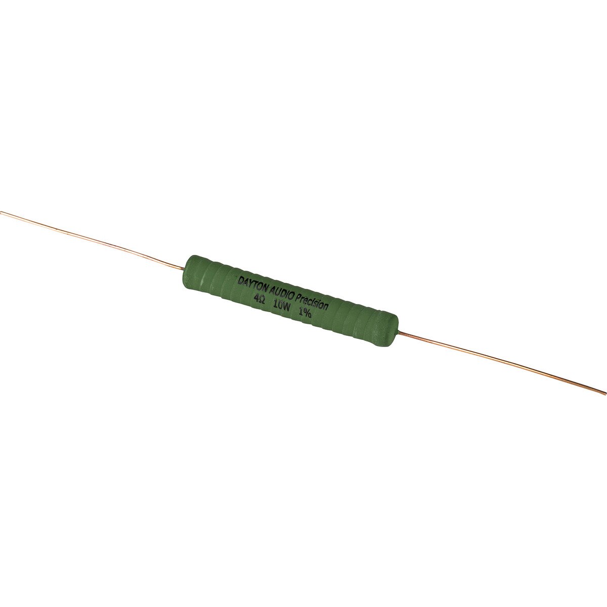
Not absolutely necessary but as long as you're in there, replace the 4 ohm resistor with one of these.
 
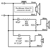
Small variations in Mini III crossover assemblies are evident from the more detailed audio forum posts. They typically appear to have identical potentiometers in Mid and Tweeter circuits, with either 5 Watt or 10 Watt midrange 4Ω series resistor and approximately 1.8µF to 2.2µF tweeter series cap.
As in this image from @JKent:

JKent Mini III assy.JPG

Rectilinear Mini III schem.png
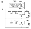
In the same Classic Speaker Pages thread, a 1970s variant shared by @ra.ra. has 8Ω series resistors in both mid and tweeter circuit, and a 2.2µF tropical-fish tweeter cap.

Mini III assy ra.ra._3.JPG
Mini III late schem.png
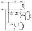
And then there's yours, with its curiously large midrange level control. From directly overhead, without a sense of its depth, it looks suspiciously like an L-pad. If true, that would change the schematic a bit:

Rectilinear Mini III schematic.png
Though maybe it's just a much higher wattage pot?
 
Last edited:
Back
Top Bottom