


cpu_
Member
I have been studying the discriminator circuit in the REL Precedent 646C-1 tuner. I would like to understand this circuit better. It's a ratio detector, according to REL literature. Here is an excerpt from the schematic.
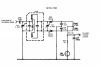
The schematic depicts an arrangement that differs from the usual schematic of a ratio detector. The primary inductance (connected to the plate circuit of the final limiter, a 6AH6 tube) is shown with connections to two other windings. Ratio detectors usually have a transformer with a center-tapped secondary winding, and a tertiary winding. In this depiction, it isn't clear which winding is a secondary, and which is a tertiary. Whatever the case, all three windings are connected at the "hot" end of the primary.
A description of the physical arrangement of these coils and the coupling and phasing would be welcomed. Has anyone opened the shield can of one of these transformers?
Another question: Were these transformers made by REL, or were they sourced by another vendor?
The schematic depicts an arrangement that differs from the usual schematic of a ratio detector. The primary inductance (connected to the plate circuit of the final limiter, a 6AH6 tube) is shown with connections to two other windings. Ratio detectors usually have a transformer with a center-tapped secondary winding, and a tertiary winding. In this depiction, it isn't clear which winding is a secondary, and which is a tertiary. Whatever the case, all three windings are connected at the "hot" end of the primary.
A description of the physical arrangement of these coils and the coupling and phasing would be welcomed. Has anyone opened the shield can of one of these transformers?
Another question: Were these transformers made by REL, or were they sourced by another vendor?


