


Dawid Ratal
New Member
Hello,
I have a problem with the relay. I replaced the power amplifiers and the famous STK3082 with the old NTC1339 (correct replacement). Well, I don't know if the diagram accurately reflects the receiver I have. I use the SR 8000 DC service manual. But I noticed that the voltage on the relay coil is 14.5V. The voltage that enters the board for the relay is 30V. According to the diagram, the emitter voltage of Q711 should be 1V, I have 14.5. Voltage on Q710 - base: 14V, collector: 14.7V emitter: 14.7V. I replaced the transistors with 2SC1400 (Q710) with KSC1845. I don't know if there is any logic in this receiver. Does the diagram differ from SR8010? I don't know where to look for the cause. The relay is TYPE MU2U 24VDC
Marantz SR 8010 DC - I use this service manual.
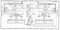
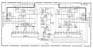
Relay board.

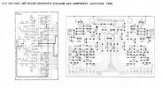

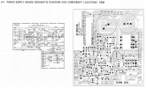
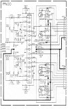
Power Supply Board. The voltage on pin J814 is the voltage to the relay.
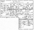
diagram
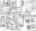
Where would you look for the cause? I would be grateful for your help.
Best!
David
I have a problem with the relay. I replaced the power amplifiers and the famous STK3082 with the old NTC1339 (correct replacement). Well, I don't know if the diagram accurately reflects the receiver I have. I use the SR 8000 DC service manual. But I noticed that the voltage on the relay coil is 14.5V. The voltage that enters the board for the relay is 30V. According to the diagram, the emitter voltage of Q711 should be 1V, I have 14.5. Voltage on Q710 - base: 14V, collector: 14.7V emitter: 14.7V. I replaced the transistors with 2SC1400 (Q710) with KSC1845. I don't know if there is any logic in this receiver. Does the diagram differ from SR8010? I don't know where to look for the cause. The relay is TYPE MU2U 24VDC
Marantz SR 8010 DC - I use this service manual.
Relay board.
Power Supply Board. The voltage on pin J814 is the voltage to the relay.
diagram
Where would you look for the cause? I would be grateful for your help.
Best!
David
Attachments

Last edited:

