• The move to the new server is done. There are some software and database maintenance updates in process. This has us passing the hat around to help out. We appreciate any donations. Seriously, even a dollar helps. The payment page may be found here - https://www.audiokarma.org/support.html

Repair noob needs help on Pioneer VSX-3800 receiver

rickie6000

New Member
Hello everyone,

I'm sure you've heard this before, but I'm a beginner when it comes to repairs and need some help on this receiver (schematic attached).

Context:
I recently got an old turntable working again, and bought a Pioneer VSX-3800 at a garage sale to listen to some records. It actually worked pretty well for a while.. until I turned up the volume. Towards the end of a record, sound stopped coming out of my speakers. I do not recall hearing a loud thump or anything, just no sound. I'm in college for Electrical Engineering so I figured I would give it a shot and open it up to see what was wrong, but I quickly got overwhelmed. I have no idea how to go about fixing this thing.

What I do know:
- I found another post on AK that mentioned measuring the emitter resistors by Q1-Q4. Indeed, the center pin on R561 measured close to 63V.
- I tested Q1-Q4 using the diode setting on my multimeter and measured 0V between two of the pins on Q3 while they were in the circuit. However, when I de-soldered them, I could not measure the 0V anymore (neither the transistor itself nor the pads on the circuit).
- I could not find any blown out resistors/capacitors at a first glance, but again, I am a beginner so I'm not exactly sure what to look for.

Any help would be much appreciated. I would love to take this as an opportunity to learn more about repairing audio gear.
Thank you all!
 
Register to hide this ad
Sounds like some output transistors are blown. Measuring 63v between the emitter resistors would indicate the transistor connected to the positive rail is blown. Try reading the voltage on the speaker outputs.
 
  • Like
Reactions: mbz
Sounds like some output transistors are blown. Measuring 63v between the emitter resistors would indicate the transistor connected to the positive rail is blown. Try reading the voltage on the speaker outputs.

I can confirm this later today, but I believe I was reading 0V on the speaker outputs. Also, how would I go about confirming whether the transistor is blown?
 
Remove the transistor from the circuit. Using the DVM diode tester, you should read ~ 0.7 v across the base emitter junction (and base to collector) if connected properly. Try both polarities if you don't know.
 
Remove the transistor from the circuit. Using the DVM diode tester, you should read ~ 0.7 v across the base emitter junction (and base to collector) if connected properly. Try both polarities if you don't know.
Thank you, I'll let you know what I read later today!
 
Also, there might be a protect relay that disconnects the speaker outputs. That could be the reason for zero volts there.
 
Diode testing of transistors, nice graphic from markthefixer below.

In circuit testing is a little tricky, keep in mind the MM test current will seek out the low resistance path, ie, when you are testing incircuit you are testing between two points, look for any alternate/low resistance paths.
 

Attachments

  • DiodeTest.JPG
    DiodeTest.JPG
    40.8 KB · Views: 13
Remove the transistor from the circuit. Using the DVM diode tester, you should read ~ 0.7 v across the base emitter junction (and base to collector) if connected properly. Try both polarities if you don't know.

Here's what I measured for the pair connected to the troubling emitter resistor.

Q1:
Base - Collector: 0.57V
Base - Emitter: 0.57V

Q3:
Collector - Base: 0.55V
Emitter - Base: 0.55V

Opposite polarity read OL for both.

Do note that I measured 0V for Q3 across some pair of the pins (I wish I note down which) when it was still in-circuit. I know that wouldn't give me an accurate reading of the transistor, but could that lead me to some other failure? These readings look pretty normal to me.
 
Yes. Q1 and Q3 look good and something else is the cause of the short. Do you have a schematic you can post?
 
Yes. Q1 and Q3 look good and something else is the cause of the short. Do you have a schematic you can post?

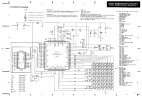
Here you go! I attached the manual I could find online. Had to convert the PDF to jpgs because the pdf was too large to upload. Page 7 has the actual output transistors on there. Thank you for all the help so far!
 

Attachments

  • VSX3800-8.jpg
    VSX3800-8.jpg
    103 KB · Views: 15
  • VSX3800-7.jpg
    VSX3800-7.jpg
    185.3 KB · Views: 18
  • VSX3800-6.jpg
    VSX3800-6.jpg
    141 KB · Views: 14
  • VSX3800-5.jpg
    VSX3800-5.jpg
    107.7 KB · Views: 8
  • VSX3800-4.jpg
    VSX3800-4.jpg
    127.5 KB · Views: 8
  • VSX3800-3.jpg
    VSX3800-3.jpg
    120.6 KB · Views: 7
  • VSX3800-2.jpg
    VSX3800-2.jpg
    106 KB · Views: 6
  • VSX3800-1.jpg
    VSX3800-1.jpg
    73.9 KB · Views: 6
  • VSX3800-9.jpg
    VSX3800-9.jpg
    139.4 KB · Views: 11
That link has parts from 4 different models. 3900, 3800, 3700 and 3600. It looks like the relevant schematic is missing for the 3800 but maybe it's similar to the 3700? Anyway, let's try this:

What do you have the ground lead of your meter connect to?
What is the voltage reading on center pin of R562?
What is the voltage reading on each pin of Q1 and Q3?

Ground lead is connected to the grounded chassis. I believe the center pin of R562 read 0V, but I can confirm that later. I'll have to resolder the transistors to measure their voltages. I'll try to find a better schematic in the meantime!
 
Hello everyone,

I'm sure you've heard this before, but I'm a beginner when it comes to repairs and need some help on this receiver (schematic attached).

Context:
I recently got an old turntable working again, and bought a Pioneer VSX-3800 at a garage sale to listen to some records. It actually worked pretty well for a while.. until I turned up the volume. Towards the end of a record, sound stopped coming out of my speakers. I do not recall hearing a loud thump or anything, just no sound. I'm in college for Electrical Engineering so I figured I would give it a shot and open it up to see what was wrong, but I quickly got overwhelmed. I have no idea how to go about fixing this thing.

What I do know:
- I found another post on AK that mentioned measuring the emitter resistors by Q1-Q4. Indeed, the center pin on R561 measured close to 63V.
- I tested Q1-Q4 using the diode setting on my multimeter and measured 0V between two of the pins on Q3 while they were in the circuit. However, when I de-soldered them, I could not measure the 0V anymore (neither the transistor itself nor the pads on the circuit).
- I could not find any blown out resistors/capacitors at a first glance, but again, I am a beginner so I'm not exactly sure what to look for.

Any help would be much appreciated. I would love to take this as an opportunity to learn more about repairing audio gear.
Thank you all!
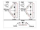
Diode mode doesn't always work in circuit. The charge in the capacitors or the other diodes in the circuit can throw off the result.

Step one should always be clean the controls with Deoxit. After that, it's electronics repair.

I am only about 5 years into repairing, my first success was an onkyo tx4500 mkii; this is how I started with only a multi meter:
1) Build a dim bulb tester; this is a requirement. It's the only way you can test voltages with the receiver on without blowing sh*t up. It costs like $10 in parts. There's tutorials all over the place.
2) learn how to read a circuit diagram, and a block diagram. I recommend the youtube video by Novalux (helped me a lot). I think it's titled "how to read a circuit diagram" or something like that; just scroll through his channel
3) Start at the power supply and test voltages that are written in the service manual. close is fine, when you find voltages that are way out of whack, that's when you start testing components.
4) If the power supply checks out, move to the amplifier. First check of the amplifier is to pull the connectors on the back and disconnect the preamp, run a signal through the amplifier (old ipod, etc.), if you get sound through the speakers, you know the power supply, amp and outputs are good, if you get no sound, the problem is not the preamp. If amplifier checks out, pull the driver transistors and check, with a multimeter, if they are good. Some people check the outputs first.
5) learn how to read a circuit diagram, and a block diagram. I recommend the youtube video by Novalux (helped me a lot). I think it's titled "how to read a circuit diagram" or something like that; just scroll through his channel

Don't quit, In this hobby, only way to learn is to do it.
 
Service manuals(hfe, tanya) are useless, they only show the rear right channel.
- I found another post on AK that mentioned measuring the emitter resistors by Q1-Q4. Indeed, the center pin on R561 measured close to 63V.

Ask, where is the 63V coming from
Chances are you will see a +65V voltage rail connected to Q2 collector, so if Q2 failed c-e short then it would be no surprise to see 60 odd volts at emitter resistors.

Another failure possibility is if the driver transistor connected to Q2 has failed c-e short dumping 60 odd volts on Q2b then 0.6Vb-e again puts 60V at emitter resistors.

Measure voltage at Q2b, it should be about +0.6Vdc, if you see +60V then driver transistor is suspected. If Q2b=0.6V then Q2 is suspected.

When performing diode test you need to test all 6 combinations including c-e (OL or short?)
 
Back
Top Bottom