• The move to the new server is done. There are some software and database maintenance updates in process. This has us passing the hat around to help out. We appreciate any donations. Seriously, even a dollar helps. The payment page may be found here - https://www.audiokarma.org/support.html

Repair: Perreaux PMF 3150

Jfaustus

AK Subscriber
Subscriber
Got this guy at auction, "untested" but a fair price in that condition. Been sitting on the pile a while. Off work today so diagnostics time. Here's what we're aiming for:

Power output: 300 watts per channel into 8Ω (stereo)
Frequency response: 20Hz to 20kHz
Total harmonic distortion: 0.03%
Damping factor: 400
Signal to noise ratio: 100dB
Speaker load impedance: 4Ω (minimum)
Dimensions: 483 x 185 x 445mm
Weight: 23kg
Year: 1986

Pretty nice!

What we're getting is both channels passing audio -- yay! Sounds great, if "great" to you means listening underwater to sounds piped through two tin cans connected by catgut. So.... BAD.

Ok, two channels of equal distortion? Power supply is our prime suspect. We can work with that. Helluva lot easier than tracking down obsolte MOSFETs.

Up next: under the hood.
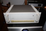
Perreaux 1.jpg
 
Register to hide this ad
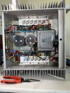
Looking under the hood and WOW! This thing was built really well. Neat layout, and I super duper appreciate how everything coming onto the PS board was screw terminals. And color coded!! Those kiwis sure are nice. Big a$$ transformer, 2x 18,000uf filter caps underneath the PS board (board screwed into the cap terminals).

IMG_4728.jpeg

image.jpg
 
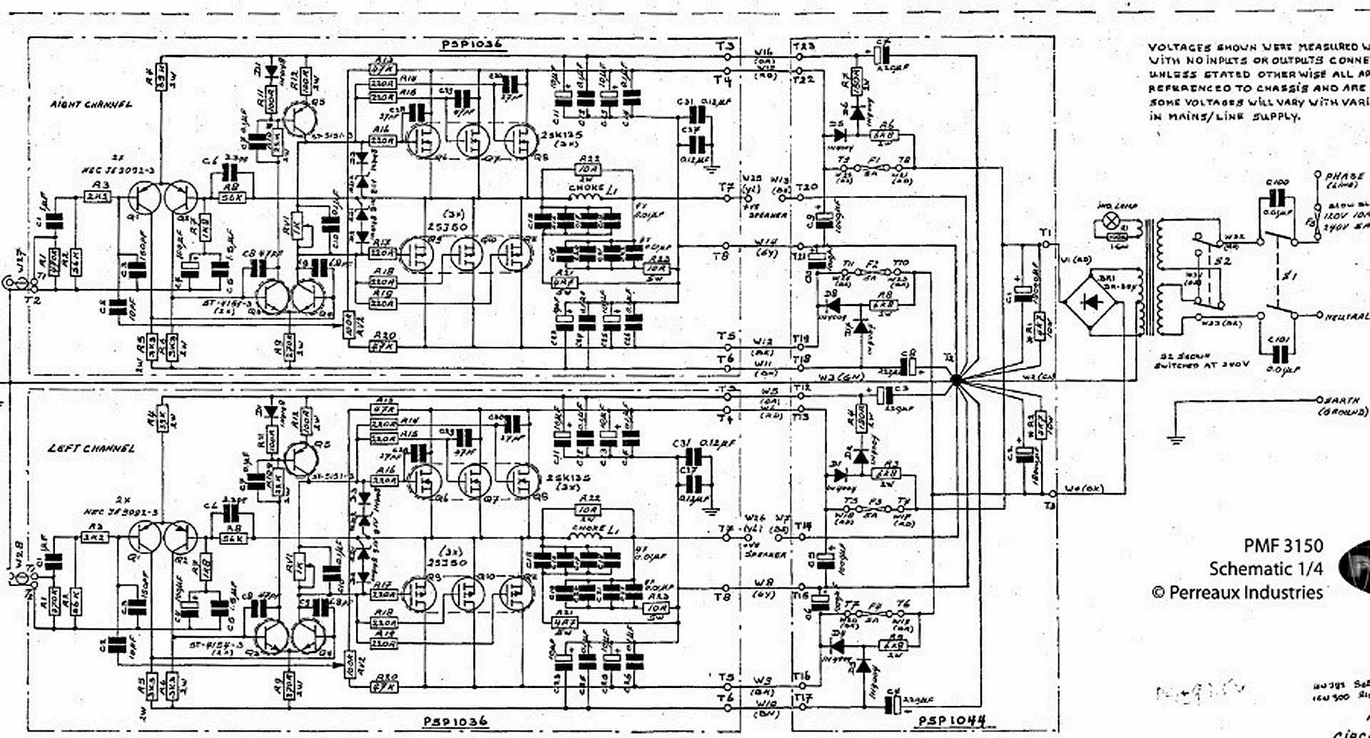
Next up, diagnostics. Immediately see that rail voltages are off. Ok so what exactly should they be? Perreaux was kind enough to give me a factory schematic, now living in the AK database. But it doesn’t show voltages. Not any…

Ok we can estimate but let’s check and confirm. Starting wit the transformer. Primary good. Mains voltage selector good. Secondary 142V before rectifier. 137V after rectifier.

Wait, what?

Let’s take a closer look at that rectifier, shall we. Is it perhaps not recitifiering as it should? Well let’s consult the AC coupled readings for each rail and see!

Nah, those look fine. Right?

Screenshot 2026-07-03 at 3.18.00 PM.pngScreenshot 2026-07-03 at 3.18.32 PM.png
 
So I'm at least replacing a rectifier. And I'll take the opportunity to check the big filter caps on the Sencore which tests for leakage at rated voltage which is quite nice.

What do you say, friends? Since she's on the operating table already would you check all the caps? Or leave well enough alone once the PS is fixed (assuming no other issues present themselves)?

Screenshot 2026-07-03 at 4.44.56 PM.png
 
Last edited:
Secondary 142V before rectifier. 137V after rectifier.
Are you sure?
142V AC ?
137V DC ?

Should be higher than 142 after the bridged rectifier. I calc it out at using 142vac. A bridge rectified dc voltage of around 200vdc. Or in your case. A 100vdc-0-100vdc as your transformer secondary is center tapped.

If not, I'd be looking at the BR and/or the main filter caps.
 
Last edited:
Are you sure?
142V AC ?
137V DC ?

Should be higher than 142 after the bridged rectifier. I calc it out at using 142vac. A bridge rectified dc voltage of around 200vdc. Or in your case. A 100vdc-0-100vdc as your transformer secondary is center tapped.

If not, I'd be looking at the BR and/or the main filter caps.
Yes I’m 99% sure the rectifier is bad.142 AC directly across the transformer secondaries, detached from the rectifier. 137 DC across the rectifier outputs after reattaching the secondaries.

The scope shots above are the positive and negative rails, AC coupled. Taken directly off the rectifier. To my untrained (but learning) eyes that looks like a ton of ripple. And also a different amplitude on each rail. All of which points to a bad rectifier, no?

This is all before the rail fuses in the power supply board. But I will definitely take your advice and double check them!
 
Big filter caps test good out of circuit. All the other caps on the PS test good in circuit. Yay!
 
9d710e5a-e4b1-4d4e-8dd2-91eb57b34558.jpg

Try to find the chart that has those nominal voltage read points (T-points) on the schematic (click on the schematic to enlarge it).

I would do this before willy-nilly changing parts.

:thumbsup:
 
Back
Top Bottom