• The move to the new server is done. There are some software and database maintenance updates in process. This has us passing the hat around to help out. We appreciate any donations. Seriously, even a dollar helps. The payment page may be found here - https://www.audiokarma.org/support.html

Repair WEGA V4810 / SONY TA5650 V-FET Solidstate Heaven By Helmuth.

Hello Helmuth,

A great job by showing pictures of the repair!

I do have a hint/warning in using a lamp when proving Vfet end stages and additionaly listening experience with film capacitors in the signal path instead of electrolytes.

LAMP or RESISTOR?
The Ffet can tolerate not more than 0.5A Ig and 5 A Ids (ref spec Vfet). The class B-drivers 2SA835/2SC1663 (original Sony design) with Ib 0.5A and 0,5W max. power dissipation are just enought for the duty, however burn often to short circuit when one of the Vfet gates has a bad value with as result that the 76V goes down and all Vfets are in audio heaven! So its imperative to prevent currents in access of 0.5 A Ig and 5A Ids!

By testing using a filament lamp with 10 Ohm cold the Vfets or drivers with a respons time of only ~10 nsecs might be destroyed before the lamp heats up (~ 0,2 secs). Therefore i prefer to use R68 5w resistors of ~ €1.50 each. With low volume sufficient for LS testing and burn-in for 24 hours.
Note that 45V / (68 +10 (Vfet gate resistor) + 10 (Driver collector resistor) + 2 ( broken trans etc) = 0.5 A

In a discussion with Sony Holland in ~1985 i got the advice to exchange the class B-drivers 2SA835/2SC1663 for heavier types 2SC1962/2SA968, they work well without fear for underrating.
Since I am now repairing a newly bought Wega 4810 and 2SC1962 is not longer available i intend to use 2SC2238/2SA968 or 2SA2344/2SC2344. Who has any experience with new drivers?

MUSIC QUALITY WITH FILM CAPACITORS
Now with 2 amps i could do a real A/B listening comparison and compare the original Wega 4810 (=TA5650) preamp (one channel) with the modified TA5650 preamp with film capacitors (other channel) with same mono signal. Remarkable improvement, much more open sound!
Any other experience?

My next TA5650 projects:
- Improvement feedback capacitor power amp
See
http://audiokarma.org/forums/showthread.php?t=74078 (nr 12 dd 16/6/2009)
- DC offset adjust
- Finding one Vfet 2SK60 (pinch-off nr 54) for my Wega 4810

Regards and a lot of Vfet audio!

Piet
 
Last edited:
Hi Piet,

I had the trimmer in the wrong corner and the lamp worked fine in preventing high current. The lamps have to heat up also the V-fet who is mounted on a heat sink.

You do not have to worry the filament is so thin it is warm fast enough.

Due the less absorption losses of the film capacitors would have to lead to more detail I would assume. And it holds for ever.


Regards, Helmuth
 
Last edited:
Hi Helmut,

You really made a nice job with this WEGA V4810.
I did almost the same with my TA5650.

The only extra thing I advise you to do is to remove the 2 connectors beetween the power supply board (+90V/-90V) and the power amplifier board.

Pic2.jpg

I have 3 TA5650 and in the younger one (serial number 506399 !) there is no connectors. All the wires are directly wrapped.

Pic3.jpg

Where did you find your NOS V-FETs ?
 
Hi Patric,

Removing the connectors is a option. I did extra work cleaning the contacts and hope this is enough to ensure good function.

Regards, Helmuth
 
Hey I solved the problem with the left channel of the preamp. :banana: And change the old capacitors for new ones also in the pre-amplifier.
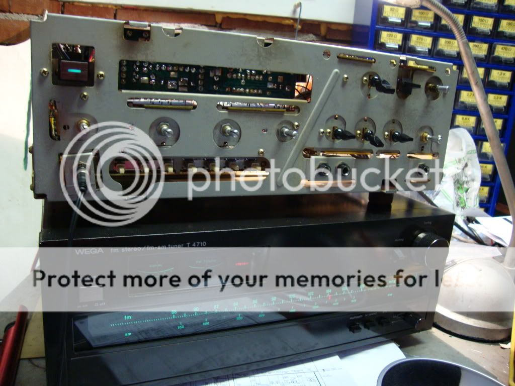
Now I can enjoy the sound of the V-Fet amp.:drool::D

DSC00250.jpg


On the end-stage nice 10 turn bias potentiometers placed.
Only thing is that I do think that the reported problems with the bias diodes can also be caused by a crappy potentiometer. I reported it to echowars he is very certain he first replaced the pot then the double diode as being the cause.

I replaced the 2.5k by a 2k type. I even could use a 1k type because it is positioned on 470 Ohm. With a 1k 10 turn you will have a very easy adjusting bias pot.
I did replace the diodes by two 1n4148 in series. And did no further research on the double diodes.
DSC00249.jpg


Regards Helmuth
 
Last edited:
After fixing the endstage there was a bop noise and a little hum on the left channel.
After switching the prestage left en right on the back. I could find out that it was the prestage right channel who caused the problem.

I hoped after replacing al capacitors the amp would sound right. This was not the case so there was something broken.
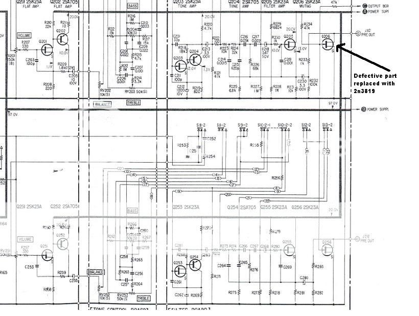
I began checking the voltages of the preamp seemed ok, after switching on with the last stage of the preamp the bop still was not gone. So my eye fell on the mute FET , (Q206, Q256) Q206 acted as a resistor. I replaced them both with the 2n3819 it is only a switch, and saved the intact 2sk23a as a spare for later.

http://www.datasheetcatalog.org/datasheet/vishay/70238.pdf


defective.jpg


new list

2SA705 by BC560B the european low noise type PNP.
2sc634a by BC546B
2sa677 by BC556B

2sa639s by 2SB648A a nice toshiba alternative also obsolete
2sc926a by 2SD668A a nice toshiba alternative also obsolete

2sk23a by 2n3819 a good replacement for the mute fets not tested in the amplifier part.

Regards Helmuth
 
Last edited:
hello to everyone
I am new here, but for a long time I have read this forum.
First I was intrested in yamaha cr2020-i had with this baby some problems that everyone else had. Now I became a memer of vfet family :) wit my wega 4810.
First thing that I changed was the 1221,and I replaced those with 1n4148.
I have now some imbalans but I will check it later.
The cr2020 is no longer a chempion....4810 is.
When I played it for the first time with my yamah cdx1050(moded) and technics sb7000 I was in deep shock how well my system can play :)

by the way , the vfets are just a littel warm (35'C)
on the speaker out put ther is 0.22mV dc and the second one has 0.18mV dc
I dont know what is the bias now-I'll check this too.

Tom
 
Welcome Intuos an update.

I am listing records on the Wega V4810 ultimate vintage experience.:rockon::guitar:

I had a Grado red and was very pleased with it, only it picket up hum. So I mounted the Shure M97eX, hum totally gone. It is also very good element neutral sound and very stable stereo image you learn to love it when you compare it to others.
specs:
site_img_us_pro_m97xe_m.jpg

http://www.shure.com/ProAudio/Products/DJPhonoCartridgesAndNeedles/us_pro_M97xE_content

Playing around with the loudnes and tone control, tone control is to much, but I like to have loudness on low medium level:thmbsp:

To the sound of the V-fet warm sound really tube like low frequency with a damping factor of 40. Compared to my other stuff I have increased the quality of the high frequency. My own tube PP-amp the high frequency sounds harder, with the V-fet it is more refined detailed.


Shure M97eX click it


Grado click it
 
Last edited:
Very nice work, Helmuth! Great pictures for those who own this rare amp. Good to see you saving the V-Fet!
 
"I am listing records on the wega v4810 ultimate vintage experience.:rockon::guitar:"

I am doing the same, i mean the vintage gear sounds best with recordings from its age.

"I had a grado red and was very pleased with it, only it picket up hum. So i mounted the shure m97ex, hum totally gone. It is also very good element neutral sound and very stable stereo image you learn to love it when you compare it to others.
Specs:
site_img_us_pro_m97xe_m.jpg

http://www.shure.com/proaudio/produ...ance to use it by the way I'am from Poland:)
 
Last edited:
I have a question for a vfet masters :)
I am wonder does the bias in vfet transistors have something to do with the sound.
In sony/wega ta-5650/4810 the factory made a mod that move the bias from 90mV to 50mV. The efect is much cooler radiator of vfets. My wega has replaced two vfets and one diode-the replacement of vfets and diode propably is conected with an accident with diode - and few resistors that mod of factory told about.
Vfets in my amp aren't even warm (???)
I am wonder does it had some influance on the sound signature, if the bias is now lower. Everybody talking about hot vfets, and my is so cool... What do you think guys about backing to the first lunch parameters- 90mV bias?

Thanks for help.
Tom
 
Last edited:
Bias Vfets @ Distortion

I have a question for a vfet masters :)
I am wonder does the bias in vfet transistors have something to do with the sound.

Hi Intuos, welcome to the forum!

Yes, low bias gives crossover distorsion and probably a bad workpoint for positive temperature compensation (Vfets do have a PTC characteristic).
I did some temperature and distortion measurements with oscilloscope and could see very clearly distortion goes to zero with bias current above 28 mV on test point (TA5650). So, I made a choice for 30 mV (~100 mA in R 0.33 = equivalent of 50mA every Vfet), since higher bias does not improve oscilloscope picture or sound quality. Why Sony originally stated 90 mV I don't known, nowhere in the literature I found requirements for operating with hot Vfets.

See my earlier answer and full story:
http://audiokarma.org/forums/showthread.php?t=74078 (nr 12 dd 16/6/2009)

PS: Change a.s.a.p. all double diodes (4 in total), they could fail any moment; I lost 4 Vfets!

Regards, Piet
 
Last edited:
Hi RealWorld :)

Thank you for your help and for an advice.
I have already changed all 4 diodes- I did that first day when this wega baby showed up in my house. When I looked on the pcb board there were parts that have been already changed- one diode, few resistors and two vfets. I checked parts tha manual advice to change and all resistors and capacitors, and bias were changed. Probably the service did that when my wega went there for repair. My bias is between 46-49mV, does it ok if the bias is "waveing" 46,48,47,49,47...etc....?

What is strange for me is that temperature of my vfets is about 34-36'C, the heatsink has room temperature.-30min of playing on normal listen level.
here are the chceck points of bias (I just what to know do I check it right)


Tom
 
Last edited:
The service manual states to connect a DC voltmeter across the speaker terminals. DC voltage should read 0 volts +-50 mV. DC bias adjustment is on RT301 and RT351 for 90 mV reading on the meter with no input signal. The positive lead should be connected on the checkpoint on the corner of the power amp board component side. There is one checkpoint on each extreme corner outboard of the adjusting pots. The negative lead should be connected to the positive speaker terminal.


If I chceck the bias like the brief above saying the bias show me 1mV, but when I checking the bias between left speaker + and right point on the pcb board it show me 47mV.
I don't know waht to think about it. My vfet are cold no metter how long the amp is turned on.

How can I chceck the vfets?
 
Hello Intuos,

May be some misunderstanding ? There are 2 important measurements:
a) DC-offset Ls terminals: should be within +/- 50 mV each channel. Normally +/- 8 mV DC without signal. The smaller the better! You can only change this in the TA5650 design by new differential transistors (Q302/303 & 352/353) to be paired for same Hfe and Vbe. A selection can be made from say 10x BC556 from the same batch/manufacturer. Hfe originally ~200. BC556 is cheap and a better replacement than Sony original.
b) Bias each channel with adjusting resistor RT301/RT351 to be 30 up to 50 mV (testpoint print left/right /+ LS output)
So your bias 1mV is far too low and it should be possible to correct with bias pot.

Bias is indeed varying a little after temp. stabilising without signal (+/- 2 mV) but check resistance of R306/356 (basis Q 301/351). This should be 33k instead of the 68 K in the documentation for better stability as already modyfied by Sony in some TA5650's.

Q: "my vfets is about 34-36'C"
A: Could be all right, expecially when shortly ago serviced with new cooling grease. Check bias for 30/50 mV !
See my temp.measurements: http://audiokarma.org/forums/showthread.php?t=74078 (nr 12 dd 16/6/2009)


Q: "How can I check the vfets?"
A: Search several threads.
In short:1 up to 2 Ohm between S and D and diode measurement between Gate and S or D. Check for same Ranking number (53/58) of same channel each polarity!
Conclusive testing: More difficult; ask when neccesary (Gives better power distribution each Vfet and longer lifetime).
Succes,

Piet
 
ok this is how all is look like:

dc offset 21mV/24mV without the signal

and now bias....

check one:
speaker + R and check point on the right -> 0mV
speaker + R and check point on the left -> 47mV

speaker + L and check point on the left -> 0mV
speaker + L and check point on the right -> 47mV

when I was trying to move the RT301/351 to change the resistance:

speaker + R and check point on the right -> 0mV
speaker + R and check point on the left -> 87mV(for example)

speaker + L and check point on the left -> 0mV
speaker + L and check point on the right -> 37mV(when I'am changing the resistance of one side there is an influance on the other one)


speaker + R and check point on the right -> 0mV
speaker + R and check point on the left -> 35mV(for example)

speaker + L and check point on the left -> 0mV
speaker + L and check point on the right -> 82mV(when I'am changing the resistance of one side there is an influance on the other one)


is there possibiliti that some one changed the wires???
I realy don't know what is going on.
 
Last edited:
Strange, when not mirrowing left/right by mistake: looks like some testing is necessary!
1) Which Ls output terminal ( L or R) gives audio output with input on left channel only ? Try with seperated pre- and power amplifier on back.
2) See schematic and disconnect power supply of one channel completely, e.g. L supply +/-45V and +/-76V.

Now look for audio output L or R? And check bias adjustment.

When testing dont forget to use always temporary resistors ~R68 5W in series with + and - 45V supply. Sufficient for test with low volume without risk of blowing precious Vfets!
NB: Without +/- 76V, vfets are fully conducting with ~22 A (45/2); Ids max of Vfets only 5A, Ig-max= 0,5A, so be careful!

Succes, Piet
 
Last edited:
There are more threats to the V-fet than the doublediode's,

1)The bias potentiometer when the middle contact of the potentiometer fails to make contact=disaster.
I advise a 1K 10 turn potentiometer to replace the 2k5 one turn. You will have a smooth adjusting pot.
And you have to let the amp to heat up at normal ambient temperature adjust to the right BIAS.

2)The connectors are a weak point the +76V when they fail to make contact= disaster.

Like one previous poster you can skip the connectors and make a sturdy wire wrap connection.

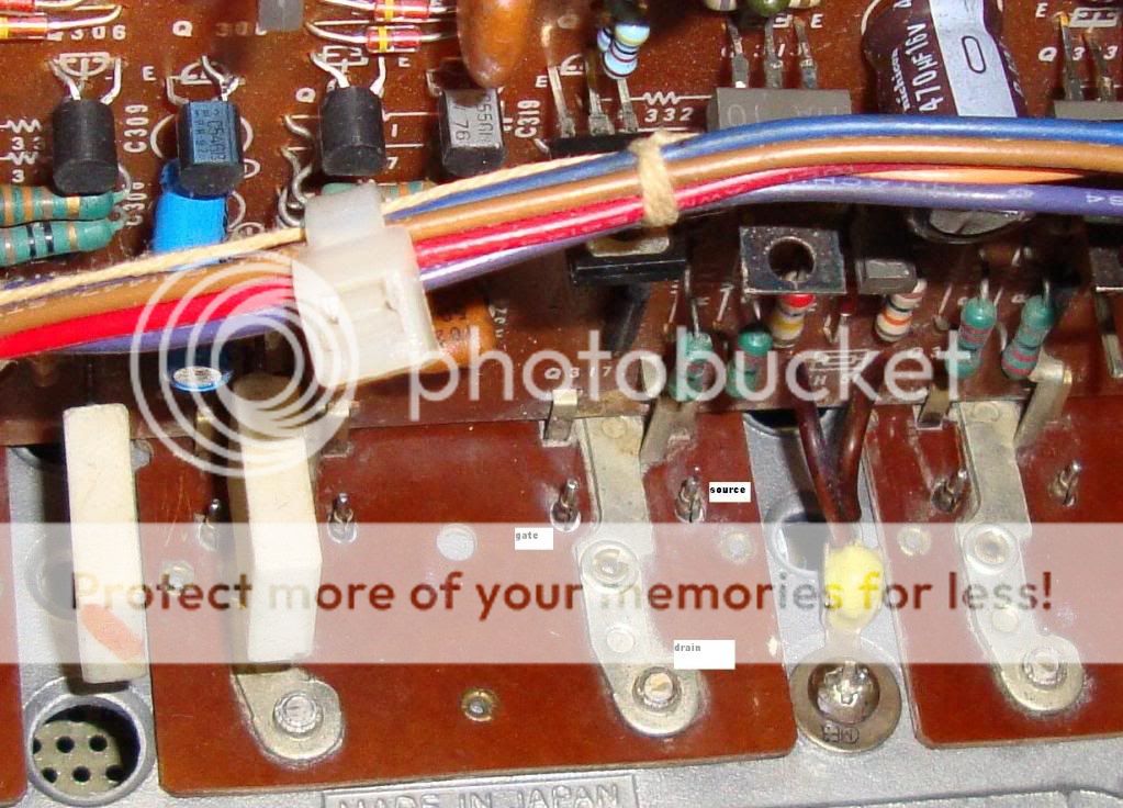
3)Also the gate has to make contact with the fitting when ONE fails disaster. So clean the contact and make sure with a resistance measurement that it makes contact.
zoomconnect.jpg


Regards, Helmuth
 
Last edited:
There are more threats to the V-fet than the doublediode's,

1)The bias potentiometer when the middle contact of the potentiometer fails to make contact=disaster.
I advise a 1K 10 turn potentiometer to replace the 2k5 one turn. You will have a smooth adjusting pot.
And you have to let the amp to heat up at normal ambient temperature adjust to the right BIAS.

2)The connectors are a weak point the +76V when they fail to make contact= disaster.

Like one previous poster you can skip the connectors and make a sturdy wire wrap connection.


Regards, Helmuth

Thank you gus for support and help.
Helmut i have already changed the old potentiometers for 10 turn 2k.
On my power amp PCB ther is a wire that I think none of you guys have on your wega/sony pcb, I will make some photos to show you this-there is a wire wich is crossing all pcb from the left to right and ist joined in two points- maybe this wire make autobias between left and right???
last night my friend visited me and we were listened to the music for about 2h
after this quite loud sesion the vfets were just a littel bit warmer, but I could touch them without be warry to burn my finger. It makes me think that bias is on realy low level.
 
Last edited:
Thank you gus for support and help.
Helmut i have already changed the old potentiometers for 10 turn 2k.
On my power amp PCB ther is a wire that I think none of you guys have on your wega/sony pcb, I will make some photos to show you this-there is a wire wich is crossing all pcb from the left to right and ist joined in two points- maybe this wire make autobias between left and right???
last night my friend visited me and we were listened to the music for about 2h
after this quite loud sesion the vfets were just a littel bit warmer, but I could touch them without be warry to burn my finger. It makes me think that bias is on realy low level.
With a bias of 50mV=150mA every enstage dissipates 13W so in total 26W. The same as there is a light bulb inside of 26W to the fingers the case is a plasant warm temperature. I estimate about 40 degrees.
 
Last edited:
Back
Top Bottom