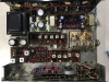
I recently picked up a Sansui 3000 from an Estate Sale and only the right side is functioning. I opened it up and wow is it gorgeous inside! It appears as if one of the 2 or 2.5 fuses keeps blowing. I replaced it and it worked for a moment and then blew again. Any ideas from those who are familiar with this model? I am an amateur and any help would be greatly appreciated! I'm guessing it's a transistor problem here. Thanks Again


You are using an out of date browser. It may not display this or other websites correctly.
You should upgrade or use an alternative browser.
You should upgrade or use an alternative browser.
Register to hide this ad

This model has a long and storied history of stability problems. There have been numerous threads here regarding repair and restoration (including mods to improve operating stability), as recently as about 2-3 months back.
A search of the forum for should yield these pretty easily. Be advised that getting these running right (and not risking your speakers) is apparently a rather difficult project, perhaps not well suited for a first effort for someone just cutting their teeth. There is much assistance to be had here, however.
Here is one to get you started, albeit for the 3000A which was an update of the 3000.
http://audiokarma.org/forums/index.php?threads/sansui-3000a.472919/
A search of the forum for should yield these pretty easily. Be advised that getting these running right (and not risking your speakers) is apparently a rather difficult project, perhaps not well suited for a first effort for someone just cutting their teeth. There is much assistance to be had here, however.
Here is one to get you started, albeit for the 3000A which was an update of the 3000.
http://audiokarma.org/forums/index.php?threads/sansui-3000a.472919/

dly66
Addicted Member
I have been enjoying a 3000A for the last month or so, it is a very good sounding receiver. I also have had a 2000A for several years and the Sansui models of this era are solidly built and pretty appealing inside and out. Spent the late fall into January doing the restoration. They are a good bit of work. The Sherwood S-8900A on the bench right now has been a breeze by comparison. Both fix and repair units bought relatively cheap. The 3000A was only $34 plus shipping from an auction on the 'bay. The seller said it had blown fuses which may have scared away buyers. I took the gamble - I knew it was going to need an overhaul to be trusted. Big question was the tuner working well - fortunately it does.
Probably not a beginner project. Can be done, takes research, patience, and practice. One thing about the old Sansui models of this vintage for the beginner is their tendency to have the component leads pressed flat against the solder traces before they applied solder which makes component removal without trace damage a bit challenging.
One thing to figure out first has it had the recommended service bulletin modifications done to it. They had a tendency to blow up and take out woofers in the process so Sansui engineers came up with some modifications back in the early '70s to help stabilize the amp and block dc from the speakers. The service bulletin and service manual for a 3000 (bulletin also applies to the 3000A) can be found at hifiengine (free to join):
https://www.hifiengine.com/manual_library/sansui/3000.shtml
The modifications included replacing the eight diodes on the driver board, changing the resistors at the output transistors, adding resistors, and putting a bipolar capacitor between the output transistors and the speaker terminals to block large DC voltage from attached speakers.
Some like running them in the original state say the mods kill the bass response. Either way its one that may be a good idea to annually check the dc offset and tweak the bias. Would not take long to do with some experience. Still I get the impression the original diodes were a weak point in the original design.
If one of those fuses are trying to blow one of the first suspicions would be a blown output transistor. Output transistors tend to fail by shorting the collector to the emitter so a quick check can be done with a voltmeter. A shorted output transistor will quickly blow a fuse. The output transistors are on the back panel, the main case is the collector, one pin the base, and the other pin the emitter. The NEC 2SD218 that were in mine had E and B to mark the pins. Mine has a set of new On MJ21194 transistors on the back of it now.
If bias is way off the fuses might blow. Dirty/tarnished trimmer resistors going open can cause the bias to be high potentially blowing output transistors. Adjusting the bias on this model is a bit tricky, most amp circuits have one bias adjustment but this one you bias each output transistor. So turning up the bias on one output transistor on a channel also ups the bias for the other. The bias for both transistors have to be nearly identical to have a low dc offset at the output. Dummy load and two if not three trustworthy voltmeters makes it easier.
A home built dim bulb tester can be your friend. Use it when plugging in unknown status units, when adjusting bias the first time, and after doing work on them such as replacing components. If something is causing the unit to draw too much current the bulb will be bright which can be the cue for you to kill the power and also having the light bulb in series with the unit if it tries to draw a lot of current the bulb filament will cause a substantial voltage drop from 120 Vac which can keep something from going pop. Mine built with parts from HD with a recycled power cord on a scrap board. There are ways to make an even more rudimentary one than mine. Usually use 60W bulb for lower power units (<40 wpc) then step up to 100W above that.
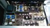

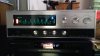
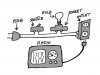
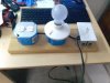
The top view is when work was done, bottom view part way through. What is important in the bottom view is the U-shaped plate at the top that I have the capacitors on a perf board bolted to it on nylon spacers. If yours has had the service bulletin work done to it with the Sansui supplied parts the plate there should have two bipolar capacitors attached to it held in brackets similar to the one the power supply filters caps by the transformer are clamped into (filter caps are blue in mine). Having 2 amp fuses suggest yours may have had the mods. Originally they had 4 amp fuses installed.
Probably not a beginner project. Can be done, takes research, patience, and practice. One thing about the old Sansui models of this vintage for the beginner is their tendency to have the component leads pressed flat against the solder traces before they applied solder which makes component removal without trace damage a bit challenging.
One thing to figure out first has it had the recommended service bulletin modifications done to it. They had a tendency to blow up and take out woofers in the process so Sansui engineers came up with some modifications back in the early '70s to help stabilize the amp and block dc from the speakers. The service bulletin and service manual for a 3000 (bulletin also applies to the 3000A) can be found at hifiengine (free to join):
https://www.hifiengine.com/manual_library/sansui/3000.shtml
The modifications included replacing the eight diodes on the driver board, changing the resistors at the output transistors, adding resistors, and putting a bipolar capacitor between the output transistors and the speaker terminals to block large DC voltage from attached speakers.
Some like running them in the original state say the mods kill the bass response. Either way its one that may be a good idea to annually check the dc offset and tweak the bias. Would not take long to do with some experience. Still I get the impression the original diodes were a weak point in the original design.
If one of those fuses are trying to blow one of the first suspicions would be a blown output transistor. Output transistors tend to fail by shorting the collector to the emitter so a quick check can be done with a voltmeter. A shorted output transistor will quickly blow a fuse. The output transistors are on the back panel, the main case is the collector, one pin the base, and the other pin the emitter. The NEC 2SD218 that were in mine had E and B to mark the pins. Mine has a set of new On MJ21194 transistors on the back of it now.
If bias is way off the fuses might blow. Dirty/tarnished trimmer resistors going open can cause the bias to be high potentially blowing output transistors. Adjusting the bias on this model is a bit tricky, most amp circuits have one bias adjustment but this one you bias each output transistor. So turning up the bias on one output transistor on a channel also ups the bias for the other. The bias for both transistors have to be nearly identical to have a low dc offset at the output. Dummy load and two if not three trustworthy voltmeters makes it easier.
A home built dim bulb tester can be your friend. Use it when plugging in unknown status units, when adjusting bias the first time, and after doing work on them such as replacing components. If something is causing the unit to draw too much current the bulb will be bright which can be the cue for you to kill the power and also having the light bulb in series with the unit if it tries to draw a lot of current the bulb filament will cause a substantial voltage drop from 120 Vac which can keep something from going pop. Mine built with parts from HD with a recycled power cord on a scrap board. There are ways to make an even more rudimentary one than mine. Usually use 60W bulb for lower power units (<40 wpc) then step up to 100W above that.
The top view is when work was done, bottom view part way through. What is important in the bottom view is the U-shaped plate at the top that I have the capacitors on a perf board bolted to it on nylon spacers. If yours has had the service bulletin work done to it with the Sansui supplied parts the plate there should have two bipolar capacitors attached to it held in brackets similar to the one the power supply filters caps by the transformer are clamped into (filter caps are blue in mine). Having 2 amp fuses suggest yours may have had the mods. Originally they had 4 amp fuses installed.

Excellent summary. I would agree that this may not be the best unit to undertake as a first attempt, but there is plenty of support here for it.
From personal experience, the factory mods to the 3000A do not suppress the bass response. The little unit has plenty of low-end punch afterward - Almost too much at times.
Also from personal experience, the germanium devices in the tuner of the unit CAN be replaced with silicon, although it is not a plug-and-play exchange. Thanks to input from the forum, and especially encouragement from Dr. Audio, the one I found was successfully resurrected.
From personal experience, the factory mods to the 3000A do not suppress the bass response. The little unit has plenty of low-end punch afterward - Almost too much at times.
Also from personal experience, the germanium devices in the tuner of the unit CAN be replaced with silicon, although it is not a plug-and-play exchange. Thanks to input from the forum, and especially encouragement from Dr. Audio, the one I found was successfully resurrected.
Thank you Watthour and dly 66 for your kind responses! I've decided to jump into it and see what happens I'll report back soon. I actually have three Sansui 3000's now from estate sales, so if one blows it wouldn't be the end of the world for me, and as I'm now collecting these things I might as well learn how to fix them!
dly66
Addicted Member
Keep in mind these units are pushing 50 years old if not older. I think the 3000 models were produced 1967-1968, maybe as early as 1966, and the 3000A followed for 1968-1969. There is apparently a rare short lived 3500 model that was a transition between the 3000s and the later 4000 replacement. With Sansui of this vintage the third digit of the serial number is the year produced, and the fourth and fifth together the month. So mine starts 22906 so it was produced in June 1969. My old 2000A and the one I just bought are both from Feb 1970.
Since they use a lot of discrete components and were hand built, these old units tend to be repairable if you want to put the effort into it. Some units its a labor of love, the market does not put a lot of value in them but they do sound very good and some units its just having an uncommon oddball piece. I started learning how to fix them a few years ago with a $20 GW find Yamaha CA-610II (matching tuner was with it for $10) that looked great physically but had a badly distorting right channel. I looked at my collection and realized the majority are former fix or repair units. Only 2-3 were in relatively good working order when I got them. This site is a great resource from past posts to posting questions on getting help fixing them.
One of these days I will tackle the $25 SX-9000 on the shelf. I think the work it requires will make the 3000A seem easy. In those old Pioneers its not just the electrolytics, but also all the transistors they used that did not age well. It has a bunch of the infamously unreliable Hitachi 2SC458LG in it along with some others.
In the 3000 if you have a very audible background hiss on the output and if it has the 2SC693F transistors on the tone control board, try replacing them with the KSC1845 to quiet it down. Four of them were in the tone board of my Sherwood S-7200 and were hissing too. Replacing them dramatically dropped the background noise in the Sherwood. With my past history of that type and since the 2SC536 appears to be made by the same company I replaced the pair of them and the pair on the amp pre-driver card with the lower gain KSC1815. Could not find much information on that model or if it had hiss problems like its counterpart. It just seems in some of the old vintage units the low noise transistors used in the tone board did not stay low noise as they aged.
The 2SC536 may age well. The 458LG was a low noise transistor has a bad reputation for getting noisy with age but you see in the same housing the 2SC460 by Hitachi in the tuner sections of a lot of those old receivers and the tuners work just fine.
If there is hiss, like what you get on FM radio between stations if there is not muting, you might just try replacing the 693F models in the tone board first, if it has them, and see if that gets it. You may find the 2SC458LG there, both were apparently interchangeable. I have not downloaded a copy of the 3000 service manual to see what transistors they were using then. Replacing both the 693 and 536 on the tone and amp board in mine has yielded very low background noise - the background noise basically disappeared. While I was in there I just went ahead and did both.
Since they use a lot of discrete components and were hand built, these old units tend to be repairable if you want to put the effort into it. Some units its a labor of love, the market does not put a lot of value in them but they do sound very good and some units its just having an uncommon oddball piece. I started learning how to fix them a few years ago with a $20 GW find Yamaha CA-610II (matching tuner was with it for $10) that looked great physically but had a badly distorting right channel. I looked at my collection and realized the majority are former fix or repair units. Only 2-3 were in relatively good working order when I got them. This site is a great resource from past posts to posting questions on getting help fixing them.
One of these days I will tackle the $25 SX-9000 on the shelf. I think the work it requires will make the 3000A seem easy. In those old Pioneers its not just the electrolytics, but also all the transistors they used that did not age well. It has a bunch of the infamously unreliable Hitachi 2SC458LG in it along with some others.
In the 3000 if you have a very audible background hiss on the output and if it has the 2SC693F transistors on the tone control board, try replacing them with the KSC1845 to quiet it down. Four of them were in the tone board of my Sherwood S-7200 and were hissing too. Replacing them dramatically dropped the background noise in the Sherwood. With my past history of that type and since the 2SC536 appears to be made by the same company I replaced the pair of them and the pair on the amp pre-driver card with the lower gain KSC1815. Could not find much information on that model or if it had hiss problems like its counterpart. It just seems in some of the old vintage units the low noise transistors used in the tone board did not stay low noise as they aged.
The 2SC536 may age well. The 458LG was a low noise transistor has a bad reputation for getting noisy with age but you see in the same housing the 2SC460 by Hitachi in the tuner sections of a lot of those old receivers and the tuners work just fine.
If there is hiss, like what you get on FM radio between stations if there is not muting, you might just try replacing the 693F models in the tone board first, if it has them, and see if that gets it. You may find the 2SC458LG there, both were apparently interchangeable. I have not downloaded a copy of the 3000 service manual to see what transistors they were using then. Replacing both the 693 and 536 on the tone and amp board in mine has yielded very low background noise - the background noise basically disappeared. While I was in there I just went ahead and did both.

McGowdog
Active Member
I have been enjoying a 3000A for the last month or so, it is a very good sounding receiver. I also have had a 2000A for several years and the Sansui models of this era are solidly built and pretty appealing inside and out. Spent the late fall into January doing the restoration. They are a good bit of work. The Sherwood S-8900A on the bench right now has been a breeze by comparison. Both fix and repair units bought relatively cheap. The 3000A was only $34 plus shipping from an auction on the 'bay. The seller said it had blown fuses which may have scared away buyers. I took the gamble - I knew it was going to need an overhaul to be trusted. Big question was the tuner working well - fortunately it does.
Probably not a beginner project. Can be done, takes research, patience, and practice. One thing about the old Sansui models of this vintage for the beginner is their tendency to have the component leads pressed flat against the solder traces before they applied solder which makes component removal without trace damage a bit challenging.
One thing to figure out first has it had the recommended service bulletin modifications done to it. They had a tendency to blow up and take out woofers in the process so Sansui engineers came up with some modifications back in the early '70s to help stabilize the amp and block dc from the speakers. The service bulletin and service manual for a 3000 (bulletin also applies to the 3000A) can be found at hifiengine (free to join):
https://www.hifiengine.com/manual_library/sansui/3000.shtml
The modifications included replacing the eight diodes on the driver board, changing the resistors at the output transistors, adding resistors, and putting a bipolar capacitor between the output transistors and the speaker terminals to block large DC voltage from attached speakers.
Some like running them in the original state say the mods kill the bass response. Either way its one that may be a good idea to annually check the dc offset and tweak the bias. Would not take long to do with some experience. Still I get the impression the original diodes were a weak point in the original design.
If one of those fuses are trying to blow one of the first suspicions would be a blown output transistor. Output transistors tend to fail by shorting the collector to the emitter so a quick check can be done with a voltmeter. A shorted output transistor will quickly blow a fuse. The output transistors are on the back panel, the main case is the collector, one pin the base, and the other pin the emitter. The NEC 2SD218 that were in mine had E and B to mark the pins. Mine has a set of new On MJ21194 transistors on the back of it now.
If bias is way off the fuses might blow. Dirty/tarnished trimmer resistors going open can cause the bias to be high potentially blowing output transistors. Adjusting the bias on this model is a bit tricky, most amp circuits have one bias adjustment but this one you bias each output transistor. So turning up the bias on one output transistor on a channel also ups the bias for the other. The bias for both transistors have to be nearly identical to have a low dc offset at the output. Dummy load and two if not three trustworthy voltmeters makes it easier.
A home built dim bulb tester can be your friend. Use it when plugging in unknown status units, when adjusting bias the first time, and after doing work on them such as replacing components. If something is causing the unit to draw too much current the bulb will be bright which can be the cue for you to kill the power and also having the light bulb in series with the unit if it tries to draw a lot of current the bulb filament will cause a substantial voltage drop from 120 Vac which can keep something from going pop. Mine built with parts from HD with a recycled power cord on a scrap board. There are ways to make an even more rudimentary one than mine. Usually use 60W bulb for lower power units (<40 wpc) then step up to 100W above that.
View attachment 1441621 View attachment 1441622 View attachment 1441623 View attachment 1441624View attachment 1441630
The top view is when work was done, bottom view part way through. What is important in the bottom view is the U-shaped plate at the top that I have the capacitors on a perf board bolted to it on nylon spacers. If yours has had the service bulletin work done to it with the Sansui supplied parts the plate there should have two bipolar capacitors attached to it held in brackets similar to the one the power supply filters caps by the transformer are clamped into (filter caps are blue in mine). Having 2 amp fuses suggest yours may have had the mods. Originally they had 4 amp fuses installed.
This is a very good post.
It should be a Sansui 3000/3000a sticky. I have repaired and in some cases modified three of my four 3000As with this info.
Here's some 3000a threads I've found and perhaps participated in wrt this fine rcvr...
http://audiokarma.org/forums/index.php?threads/sansui-3000a-restoration.728452/page-2#post-12176255
http://audiokarma.org/forums/index.php?threads/sanui-3000a-volume-control-and-output.819503/page-3
http://audiokarma.org/forums/index.php?threads/sansui-3000a-speaker-prot-mod.647005/#post-11722957
http://audiokarma.org/forums/index.php?threads/3000a.7295/#post-11652697
http://audiokarma.org/forums/index....wired-in-backwards-from-factory.808886/page-3
... just to pick out a few.
Oh found another one...
http://www.audiokarma.org/forums/in...hannel-3000a-need-advice.213416/#post-2535498
Last edited:
dly66
Addicted Member
There is a website over in England run by someone who admits to being biased toward valve (tube) amps. Their review of the 3000A helped push me to gamble on one. I was about to sniper bid on one before going at a good price but someone lit up my phone with texts and I submitted the bid too late. Took a gamble on the one I got. They like them a lot but do say they are a bit tricky and have some detailed comments on them. They review both the 3000 and later 3000A.
http://select45rpm.com/pages/hifi/vintage-hifi-reviews.html#176
They review a number of vintage units. I own the Sherwood S-7200 and Yamaha CR-800 which are both reviewed. The S-7200 has a quirky amp design but is very good sounding, especially the FM tuner section.
On mine after the service mods I found about 26-27 mV across the 1 ohm resistors attached to the output transistors drew about 76 ma at the fuses. Someone had suggest 55 mV and I had done that and later checked the current draw on one channel with both fuses out and voltmeters in current mode and found it was drawing about 96 ma across both fuses. The Sansui manual has 80 ma as the desired current draw at idle. That put mine within 5% of the target and it stays cooler at the lower bias.
http://select45rpm.com/pages/hifi/vintage-hifi-reviews.html#176
They review a number of vintage units. I own the Sherwood S-7200 and Yamaha CR-800 which are both reviewed. The S-7200 has a quirky amp design but is very good sounding, especially the FM tuner section.
On mine after the service mods I found about 26-27 mV across the 1 ohm resistors attached to the output transistors drew about 76 ma at the fuses. Someone had suggest 55 mV and I had done that and later checked the current draw on one channel with both fuses out and voltmeters in current mode and found it was drawing about 96 ma across both fuses. The Sansui manual has 80 ma as the desired current draw at idle. That put mine within 5% of the target and it stays cooler at the lower bias.
Last edited:

fandersen
Active Member
I received my 3000a from a friend who had a couple spare ones. The one he gave me was cosmetically very nice but it didn't sound very good. I popped the hood to see if the service bulletin mods had been applied. They had, but not according to Sansui’s instructions. Instead of installing the bipolar caps on the speaker outputs, they had replaced two of the filter caps with the bipolar caps.

The resistors had been replaced but not the diodes on the Pre-power (TRZ-2D) board, probably the Achilles heal off this receiver. Someone had recently been in the amp as it had new output transistors and a few caps replaced.
The design of the 3000a is interesting as it is a quasi-complementary amplifier with inter-stage transformers and separate power supply for each channel. Looks like a good design and as mentioned by dly66, highly reviewed by Select45rpm. So I decided to completely rebuild the amp starting with the Pre-power board. I checked the 2SC756 transistors and found the gain on a couple to be quite low so replaced all of them with matched KSC2690. Next tested the carbon comp resistors and found they had drifted considerably. In some cases there was 30% difference between the left and right channel. So all the resistors were replaced with matched 1% metal films. Of course the diodes and trimmers were also replaced. In the end everything on the board except the large wire wound resistors was replaced.
Moving on to the Driver Amp and Pre-Amp I found the carbon comp resistors had also drifted way out of spec. So ended up completely rebuilding them as well with new resistors, caps and low noise transistors. The rest of the boards received a complete recap, bumping up the capacitance on the power supply and installing 6,800 uFs filter caps.
The reputation of this amp was a concern and I planned to install bi-polar caps as per the service bulletin to protect my speakers. But having experienced what larger speaker coupling capacitors do for the Sansui 2000 and 4000 receivers, I wasn’t happy with just 1,000 uF bipolar caps. I therefore decided to explore installing a speaker protection board instead. After some searching I found Neurochrome had released a speaker protection board called the Guardian-686. What I liked about this board is that switching is done without relays and has a soft start. A further bonus is that you can customize the sensitivity of the DC detection circuit and the soft start by using different components. I implemented it with the default components and soldered the wires in place instead of using the Molex connectors. To power the protection board I installed an IRM-01-24 AC/DC power module. I have no affiliation with Neurochrome or vested interest in recommending the board, I just think it’s a nice alternative to some of those Chinese protection boards on eBay, albeit at a higher price.
As others have indicated setting the bias on this amp can be tricky. Ideally you want to adjust the two bias controls so you have 0.0V DC on the speaker outputs and the same bias on each output transistor. I connected a speaker load and adjusted one channel at a time using 3 DMMs connected across R016 and R017 and the third on speaker output. You don’t need 3 DMMs, it just makes the task easier. Adjusting the bias on one transistor will change the bias on the other, and the DC on the output. Make small adjustments to prevent the bias from running away on the other transistor. This is where the two meters come in handy. Once the bias is set you should have less that 5mV DC on the speaker outputs. If you don’t you will need to adjust one of the bias settings to get as close as you can to 0.0mV DC. On the first channel I found it took several tries to get the three settings correct, the second channel went much quicker. I played the amp for about a week in my shop and then readjusted the bias.
The service manual specifies a bias current of 80mA. Some people recommend a more conservative setting of 40mA so I tried 40, 60 and 80mA settings eventually settling on 80mA which sounded the best to me. With the 1ohm resistors in the service bulletin this is 80mV across each of R016-9.
I replaced the 8 Deluxe in my main listening area with the 3000a for a longer evaluation. I was immediately impressed by the openness and detail of this amp. I liked it but was hesitant to say it was just as good as the 8D, which is also completely restored. After a couple of months I decided it was time to put the 8D back in service. That lasted for about two days before the 8D was again replaced by the 3000a. I’m not saying I don’t like the 8D, it is a wonderful amplifier that I will probably keep forever, but that openness and detail of the 3000a is wonderful. I would even venture as far as to say the 3000a has more depth that the 8D. This is of course my personal opinion and experience with the 3000a, ymmv.
The resistors had been replaced but not the diodes on the Pre-power (TRZ-2D) board, probably the Achilles heal off this receiver. Someone had recently been in the amp as it had new output transistors and a few caps replaced.
The design of the 3000a is interesting as it is a quasi-complementary amplifier with inter-stage transformers and separate power supply for each channel. Looks like a good design and as mentioned by dly66, highly reviewed by Select45rpm. So I decided to completely rebuild the amp starting with the Pre-power board. I checked the 2SC756 transistors and found the gain on a couple to be quite low so replaced all of them with matched KSC2690. Next tested the carbon comp resistors and found they had drifted considerably. In some cases there was 30% difference between the left and right channel. So all the resistors were replaced with matched 1% metal films. Of course the diodes and trimmers were also replaced. In the end everything on the board except the large wire wound resistors was replaced.
Moving on to the Driver Amp and Pre-Amp I found the carbon comp resistors had also drifted way out of spec. So ended up completely rebuilding them as well with new resistors, caps and low noise transistors. The rest of the boards received a complete recap, bumping up the capacitance on the power supply and installing 6,800 uFs filter caps.
The reputation of this amp was a concern and I planned to install bi-polar caps as per the service bulletin to protect my speakers. But having experienced what larger speaker coupling capacitors do for the Sansui 2000 and 4000 receivers, I wasn’t happy with just 1,000 uF bipolar caps. I therefore decided to explore installing a speaker protection board instead. After some searching I found Neurochrome had released a speaker protection board called the Guardian-686. What I liked about this board is that switching is done without relays and has a soft start. A further bonus is that you can customize the sensitivity of the DC detection circuit and the soft start by using different components. I implemented it with the default components and soldered the wires in place instead of using the Molex connectors. To power the protection board I installed an IRM-01-24 AC/DC power module. I have no affiliation with Neurochrome or vested interest in recommending the board, I just think it’s a nice alternative to some of those Chinese protection boards on eBay, albeit at a higher price.
As others have indicated setting the bias on this amp can be tricky. Ideally you want to adjust the two bias controls so you have 0.0V DC on the speaker outputs and the same bias on each output transistor. I connected a speaker load and adjusted one channel at a time using 3 DMMs connected across R016 and R017 and the third on speaker output. You don’t need 3 DMMs, it just makes the task easier. Adjusting the bias on one transistor will change the bias on the other, and the DC on the output. Make small adjustments to prevent the bias from running away on the other transistor. This is where the two meters come in handy. Once the bias is set you should have less that 5mV DC on the speaker outputs. If you don’t you will need to adjust one of the bias settings to get as close as you can to 0.0mV DC. On the first channel I found it took several tries to get the three settings correct, the second channel went much quicker. I played the amp for about a week in my shop and then readjusted the bias.
The service manual specifies a bias current of 80mA. Some people recommend a more conservative setting of 40mA so I tried 40, 60 and 80mA settings eventually settling on 80mA which sounded the best to me. With the 1ohm resistors in the service bulletin this is 80mV across each of R016-9.
I replaced the 8 Deluxe in my main listening area with the 3000a for a longer evaluation. I was immediately impressed by the openness and detail of this amp. I liked it but was hesitant to say it was just as good as the 8D, which is also completely restored. After a couple of months I decided it was time to put the 8D back in service. That lasted for about two days before the 8D was again replaced by the 3000a. I’m not saying I don’t like the 8D, it is a wonderful amplifier that I will probably keep forever, but that openness and detail of the 3000a is wonderful. I would even venture as far as to say the 3000a has more depth that the 8D. This is of course my personal opinion and experience with the 3000a, ymmv.
As others have indicated setting the bias on this amp can be tricky. Ideally you want to adjust the two bias controls so you have 0.0V DC on the speaker outputs and the same bias on each output transistor.
Thank you for the well explained write-up on how to set the bias on a 3000A .
This is absolutely outstanding. I hadn't logged in for some time and am so pleased to see all of this information here. I never thought I would get so much of a response. Sadly I haven't had the time yet to dig into the 3000, but find comfort that this "manual" is here waiting for me when I do, and that it is helping others
Ducksalot.......
There is a current ongoing thread started by birchoak about his 3000A that got damaged in shipping to him.
Lots of good stuff there too. I added some links there and posted about my 3000A.
Seems to me the 3000A is more common than 3000 but they share a lot that can help you.
Jef
There is a current ongoing thread started by birchoak about his 3000A that got damaged in shipping to him.
Lots of good stuff there too. I added some links there and posted about my 3000A.
Seems to me the 3000A is more common than 3000 but they share a lot that can help you.
Jef

tom3
Super Member
One thing to watch with an un-modified 3000/a when using with a turntable. The amp has no low limit to the bass response, mine will output to 10 hz. You can get feedback from the cartridge that will build up fast and trip the protection circuit in the amp with the volume turned up some. Probably depends on the turntable but watch for it.
dly66
Addicted Member
One thing to watch with an un-modified 3000/a when using with a turntable. The amp has no low limit to the bass response, mine will output to 10 hz. You can get feedback from the cartridge that will build up fast and trip the protection circuit in the amp with the volume turned up some. Probably depends on the turntable but watch for it.
Historically that was what the Low Filter on the 3000A and other vintage audio was for, some manufacturers may call it a subsonic filter. It is meant to filter out the low frequency content, particularly the rumble from the turntable.
From the 3000A Owner's Manual:

Curious to know how you mounted the KSC2690As to the heat sinks and soldered to driver board. There is also what might be called a pre-driver board. Did you replace the two can style transistors on there too? TRD.6B board. If you did replace those, did you also use KSC2690A as subs there?
Also, the output transistor emitter resistors, do you recommend 1 ohm 5 watt?
The diodes on the driver board, what part # did you use there?
Lots of questions because there have been many different suggestions by different people.
Thx in advance,
Wayne
Also, the output transistor emitter resistors, do you recommend 1 ohm 5 watt?
The diodes on the driver board, what part # did you use there?
Lots of questions because there have been many different suggestions by different people.
Thx in advance,
Wayne