• The move to the new server is done. There are some software and database maintenance updates in process. This has us passing the hat around to help out. We appreciate any donations. Seriously, even a dollar helps. The payment page may be found here - https://www.audiokarma.org/support.html

Repairing or gluing a broken PCB board and circuit traces

dlucy

dlucy67 (Doug)
Staff member
Moderator
Subscriber
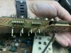
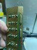
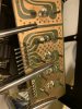
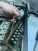
I am restoring a buddy’s Hartman Kardon 730 twin series receiver today and I’ve found why none of the external inputs work: the rear panel RCA jack input board is physical cracked or broken and that has broken traces and interrupted the circuit path.

192CDAA8-AE6D-4FC5-A714-35B4B71E7BE8.jpeg
25D91B65-46C2-4EC5-AE3D-4B088BF4F21C.jpeg
303340B7-A4A2-475A-B3ED-CE0D4B2E25BC.jpeg
9572972E-3687-4FC9-8834-D968DD6146EC.jpeg
1C3D5CBA-C85A-4D4C-8ED4-A86155C59C65.jpeg
687D6992-2D5A-4181-A41C-8842F30EEF1E.jpeg

I’m thinking I can clean the two mating surfaces with some IPA, blow it out, bend the two pieces mostly back together, dropper some super glue in the crack, close the two faces together, then hold the broken board faces together for an hour with hemostats clamping across the two sides of the board.

Then carefully make solder bridges across all the broken traces. For any wide gaps I’ll cut 2mm long station wire pieces and solder one across the two sides of each broken traces.

Is there a better, smarter way, AK? Help me help a fellow AK’er with some sage advice, please.
 
Register to hide this ad
I agree, epoxy and wire bridges. I'd also want to splint it if I could, but it appears you have traces on both sides of the board (is that correct?)

Were there screws missing from the RCA panel prior to the damage (and thus stress on the board, from cables being plugged in and out?) If so, that should be eliminated, of course, before putting it back into service.

Another possibility... if there aren't any devices on the other side, can the board and wire it point to point.
 
Yep... A epoxy and slightly scrape the laminate off the traces and wire jump. On another similar thread gorilla glue was suggested , I have always been a 5 minute epoxy man but found out the I liked the gorilla better after trying it. Just watch out where the water gets as thats the catalyst and follow the instructions. I would avoid super glue for this one though. This project should work out OK for you.:)
 
Note: When jumping across the broken traces, scrap off the top exposing shiny copper. Then solder across with solid copper wires.

I like epoxy over super glue in this application.
 
I agree, epoxy and wire bridges. I'd also want to splint it if I could, but it appears you have traces on both sides of the board (is that correct?)

Were there screws missing from the RCA panel prior to the damage (and thus stress on the board, from cables being plugged in and out?) If so, that should be eliminated, of course, before putting it back into service.

Another possibility... if there aren't any devices on the other side, can the board and wire it point to point.

Splint makes good sense. Excellent!

Yes, the bottom most screws were missing and I didn’t understand why until you pointed that out. Yep, you’re right.
 
Epoxy will leave gaps since it needs to be physically between the two parts. Crazy glue will leave no gaps as it soaks into the fiberglass. Crazy glue is just better with porous surfaces.

I think that’s a good approach, especially if combined with epoxy on the surface of the board with wood splits, maybe cut down popscicle sticks, to hold the tops of the boards together. Excellent.
 
Note: When jumping across the broken traces, scrap off the top exposing shiny copper. Then solder across with solid copper wires.

I like epoxy over super glue in this application.

Yep. I’ve got solid core copper wire, so I’ll strip that down bare and use that instead. Good idea.
 
Once repairs are complete and verified, clear epoxy coating can be applied to the solder side of the board as reinforcement for the CA adhesive used to hold the fibrous board together. I've had good success with urethane epoxy clearcoat automotive finish for this purpose.
 
Once repairs are complete and verified, clear epoxy coating can be applied to the solder side of the board as reinforcement for the CA adhesive used to hold the fibrous board together. I've had good success with urethane epoxy clearcoat automotive finish for this purpose.

That’s cool. Any worries about epoxy being conductive or capacitive?
 
My forte is industrial electronics, and frequently in awful environments. Coating is not optional, but mandatory to keep out conductive contaminants, humidity/moisture from all manner of sources, corrosive atmospheres, etc. I've used PPG/Omni MC270 with MH277 catalyst with very good success. FWIW, the bus voltages on a typical "480V" VFD are often over 800VDC, and while carriers seldom reach the RF ranges the switching frequencies are typically into the 12-15 KHz ranges. I have no problems with that coating introducing resistance nor capacitance.
 
Lots of good suggestions. I usually just clean, use crazy glue holding tight for 5 minutes, and then scrape the etch runs and solder copper wire across the breaks.
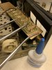
Your first picture looks like some of the hardware for that board was missing, which could have caused the board to break. (I only see 2 of the 6 screws on place. You should make sure all the screws are in place when you finish
 
My forte is industrial electronics, and frequently in awful environments. Coating is not optional, but mandatory to keep out conductive contaminants, humidity/moisture from all manner of sources, corrosive atmospheres, etc. I've used PPG/Omni MC270 with MH277 catalyst with very good success. FWIW, the bus voltages on a typical "480V" VFD are often over 800VDC, and while carriers seldom reach the RF ranges the switching frequencies are typically into the 12-15 KHz ranges. I have no problems with that coating introducing resistance nor capacitance.

Perfect. That is a relief. I don’t want to interfere with the input signals as a result of repairing this board.
 
Lots of good suggestions. I usually just clean, use crazy glue holding tight for 5 minutes, and then scrape the etch runs and solder copper wire across the breaks.
Your first picture looks like some of the hardware for that board was missing, which could have caused the board to break. (I only see 2 of the 6 screws on place. You should make sure all the screws are in place when you finish

You nailed it. There were only two of the six screws installed and those were shiny zinc coated new ones. I’ll correct that once the board is back in one piece.
 
Yes solder wire across the tracks. Like the idea to hold the PCB together. At work after bridging a broken track. I cover the repair with a spot of conformal coating to hold the fix in place. Wonder who dropped the unit. Will try to find out the coating we use a work.
 
Last edited:
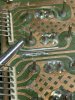
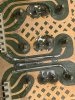
Edges held together with hemostats and instant cure (thin) CA applied. That worked well.

Bridges made with solid wire and solder. Not pretty but solid.

E30F8789-EE89-47BC-906A-DB769BC924A6.jpeg
A9EDAE91-F4D2-47DF-B9A7-00F600AA7F4E.jpeg
92A2256D-52BE-44DA-A7C4-E9DF2031356F.jpeg
F9B59725-D0EC-4DA0-8150-3B8D6340900E.jpeg
59FFDB06-5C98-4C48-ABB5-6C0C03BDCEBD.jpeg
7F544F62-F8E8-411A-8337-41D3A0FD8CDF.jpeg

Now to make a plan on how to apply (and fence-like retain) 30 min epoxy on top of all that.
 
Back
Top Bottom