• The move to the new server is done. There are some software and database maintenance updates in process. This has us passing the hat around to help out. We appreciate any donations. Seriously, even a dollar helps. The payment page may be found here - https://www.audiokarma.org/support.html

Repairing Technics SA-600

KixBit

New Member
Hello all,

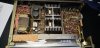
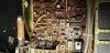
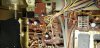
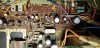
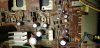
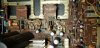
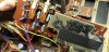
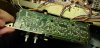
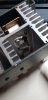
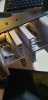
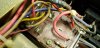
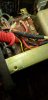
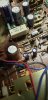
I've come across this Technics SA-600 that's been in storage for a couple decades, and decided to try getting it running again. Though the external speaker protection fuses are fine, the F2 fuse inside continually blows. I saw in this thread https://audiokarma.org/forums/index.php?threads/cleaning-technics-sa-600.669534/ that all three fuses blowing likely indicates a ruined power amp section. However, might there be hope for this one, with only one fuse blown? I've attached some pictures I've taken of the internals. Maybe I've missed something? The rust on the transformer is suspicious to me, but who knows? If anyone has had experience working on these, I'd be really appreciative of any help you can give.

Aloha from Hawaii!
 

Attachments

  • 20201018_171543.jpg
    20201018_171543.jpg
    98.9 KB · Views: 70
  • 20201018_171559.jpg
    20201018_171559.jpg
    122.8 KB · Views: 65
  • 20201018_191305.jpg
    20201018_191305.jpg
    98.1 KB · Views: 64
  • 20201018_191308.jpg
    20201018_191308.jpg
    114.2 KB · Views: 61
  • 20201018_191312.jpg
    20201018_191312.jpg
    112.8 KB · Views: 61
  • 20201018_191315.jpg
    20201018_191315.jpg
    123.3 KB · Views: 59
  • 20201018_191319.jpg
    20201018_191319.jpg
    116.8 KB · Views: 59
  • 20201018_191331.jpg
    20201018_191331.jpg
    84.3 KB · Views: 57
  • 20201018_191334.jpg
    20201018_191334.jpg
    116.3 KB · Views: 54
  • 20201018_191337.jpg
    20201018_191337.jpg
    127.5 KB · Views: 63
Last edited:
Register to hide this ad
Some more pictures if that's helpful
 

Attachments

  • 20201018_191340.jpg
    20201018_191340.jpg
    105.9 KB · Views: 24
  • 20201018_191347.jpg
    20201018_191347.jpg
    98.1 KB · Views: 20
  • 20201018_191357.jpg
    20201018_191357.jpg
    99.3 KB · Views: 16
  • 20201018_191402.jpg
    20201018_191402.jpg
    90 KB · Views: 21
  • 20201018_191922.jpg
    20201018_191922.jpg
    51.8 KB · Views: 23
  • 20201018_191934.jpg
    20201018_191934.jpg
    46.2 KB · Views: 22
  • 20201018_191947.jpg
    20201018_191947.jpg
    57.4 KB · Views: 22
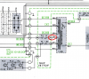
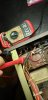
Update: I tried making some measurements, and found that one end of the fuse holder was shorted to ground. Specifically, the part of the fuse holder that connected to the transformer, wire 47 (yellow). I don't think that this should be ground, since wire 40 (blue) should be ground. Likely the winding has corroded and shorted. I've ordered a replacement, and let's see if that fixes the issue.
 

Attachments

  • Screenshot 2020-10-18 220634.png
    Screenshot 2020-10-18 220634.png
    592.4 KB · Views: 30
  • 20201018_220936.jpg
    20201018_220936.jpg
    100.4 KB · Views: 31
  • 20201018_221017.jpg
    20201018_221017.jpg
    94.9 KB · Views: 30
  • 20201018_221048.jpg
    20201018_221048.jpg
    72.7 KB · Views: 30
Keep in mind that measuring between pin 47 and chassis you could be measuring the secondary winding resistance, ie between
pins 47 and 40(blue wire). Exactly what resistance are you seeing, 0.6ohms?
EDIT: OK 2.2 ohms, bit high for a short
 
With F2 removed, measure resistance between pin 49 and chassis.

Suggest check downstream components for signs of stress and failure,
- D703, diode test
- R704 68/5W stress?
- C707, 708 stress?
- Q701, diode test
- C705, 706 stress?
 
The precise measurement is 0.9 Ohms, the connection was a bit weak while I was taking the picture.
What is the reading when probes shorted/touching each other, this is the probe/leed resistance that you would subtract from the 0.9...

Try measuring resistance between pins 32 and 37 (other secondary winding). Ballpark same Vac, turns,,,
 
Hi mbz,
With F2 removed, there is no connection between pin 49 and chassis.
D703 passes a diode test
R704 appears good, has a measured resistance of 67.4 ohms.
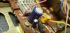
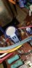
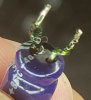
C707 has some sort of oily reside on the plastic sleeve around it. I'm not sure if its the plastic melting or the capacitor leaking.
C708 appears ok
Q701 passes a diode test, fwd bias on base(+) to collector(-), base(+) to emitter (-), and collector(+) to emitter(-). reversing the leads shows no connection.
C705 appears ok
C706 appears ok
The probe resistance is 0.2 ohms.
Pin 47 to 40 is 0.8 ohms after subtracting probe resistance
Pin 32 to 37 is 0.4 ohms after subtracting probe resistance

I've included some pictures of the capacitors.
 

Attachments

  • 20201019_180928.jpg
    20201019_180928.jpg
    68 KB · Views: 25
  • 20201019_181240.jpg
    20201019_181240.jpg
    77.9 KB · Views: 25
  • 20201019_181534.jpg
    20201019_181534.jpg
    74.7 KB · Views: 25
  • 20201019_180845.jpg
    20201019_180845.jpg
    88.3 KB · Views: 24
Thinking that the fuse holder (post #3) is not the issue and the low resistance reading
is for the transformer secondary (pins 47&40). There is no hard short (pin 49&GND) so
possibly something is failing under load/volts. Caps would be a prime candidate, you
could try replacing C707 220uf/50V, "anything" would do, prefer Nichicon UPW or similiar,
ok to go up in uf and volts if you have something handy. You can even remove C707 for a test.
Also, you should build a dim bulb tester, a current limiting device, numerous plans on AK.
 
Ok, got it. Ordered some replacement caps, and I'll start assembling a dim bulb tester. I'll update once the parts come in. Thank you for your help so far!
 
I've got an update. I received a full recapping kit for the SA-600, replaced all caps with new ones. In the process, I found that C903 had a pool of green gel underneath it, it had likely failed. Pictures are attached. Built a DBT, and used it for testing. On first power on, the front panel bulbs did not light (they previously did), and the input select LEDs were lit (they previously were not). The input select LEDs changed with the input select knob. The DBT bulb was on, medium bright. The safety LED was not lit. No sound came out, and the power level LEDs were not lit. As I troubleshooted, I found that I had forgot to solder the joint for pin 50 on the fuse board. I turned off the system, soldered that joint, then turned it back on. Now, the DBT lights up fully bright. The receiver does not light up at all. Without the DBT, fuse F1 blew. I think this may be significant, as initially, F2 was the fuse that blew. I've tried checking the rest of the solder joints I have made. They seem to be ok visually. The resistance between the input leads to the power transformer is 1.5 Ohms. I also tried checking the resistance of R1003, but it's value is higher than my meter can read (it's value is 3.3 M, mine stops at 2M). If anyone has any ideas, I would appreciate it. My next suspison would be the transformer, given it is a little rusty on the top. But if anyone has any other troubleshooting ideas, I'll give it a shot! Thank you!
 

Attachments

  • 20201116_205158.jpg
    20201116_205158.jpg
    61.6 KB · Views: 26
  • 20201116_205209.jpg
    20201116_205209.jpg
    109.3 KB · Views: 24
Been a while so take some time to come up to speed.

At power on, the DBT should glow briefly for a few seconds then dim off.
Suggest you only power on with DBT connected until it behaves as above, by
remaining bright means that there is a (near?)short.

Remove F2 and F3, replace F1 with new fuse, power up on DBT.
If bulb remains bright then (new) problem with power amp. Remove R649 and R651 then power up on DBT.
If still bright then diode test Q609-616(error in schematic).

If DBT dims with R649, R651 removed then problem is downstream one of these resistors.
 
@mbz
I replaced F1, removed F2 and F3. I removed R649 and R651. I found that R651 was discolored and failed a continuity test. Powering on with the DBT, the bulb was brightly lit. I tried removing the amplifier/heatsink assembly, and the DBT behaved as you said it should, it briefly and dimly lit then turned off. I'm thinking the problem may be in this assembly. The results of diode testing the transistors in this assembly are as follows:
Left channel, Q613:
collector->emitter SHORT
collector->base equal bias in either direction

Left channel, Q614:
collector->emitter SHORT
collector(+)->base(-) GOOD

Right channel, Q613:
collector->emitter OPEN
collector(-)->base(+) GOOD

Right channel, Q614:
collector->emitter OPEN
collector(+)->base(-) GOOD

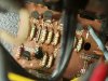
I have also attached photos of the blown resistor and transistors. All four transistors are heavily corroded, and likely the cause of the short. I read on this forum that these types of transistors are supposed to be replaced in pairs, would you know about how to find appropriate replacements? in addition, there is a lot of this white grease underneath the transistors and in the supports for the heat sink. Is it some sort of thermal paste? I cleaned off most of it and wonder if I need to replace it. Thank you for your help.

@avionic
Haha, my partner had stored this unit in a cluttered storage room, out of mind for decades. The room gets real muggy in the Hawaiian heat, no wonder its so corroded. I only found it after "encouraging" him to help clean out the room. ;) I think it's an interesting challenge to repair! I'm certainly glad to have found a community of people so knowledgeable and willing to help get these systems working again!
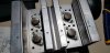
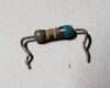
 

Attachments

  • 20201221_212030.jpg
    20201221_212030.jpg
    78.6 KB · Views: 21
  • 20201221_212043.jpg
    20201221_212043.jpg
    76.7 KB · Views: 19
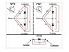
Just for future reference on diode testing, nice graphic from markthefixer, need to test 6 combinations. In any case
Q613, 614 c-e short explains the blown fuse/DBT behaviour. Will look for subs.
DiodeTest.JPG
 
Excellent, thank you for the graphic, it does help with diode testing. I also appreciate the help selecting replacement transistors.
 
Service manual has TR613(2SD665, NPN) and TR614(2SB645, PNP)
Suggest MJ21193(PNP)/MJ21194(NPN) from onsemi, 16A devices, others better at transistor matching.
Note which transistor goes where before removing.

The white grease is thermal paste, need to remove old paste from heat sink, carefully
remove mica insulator before hand, don't damage. Apply thin film to new transistor, scrape
excess off with credit card (needs to be thin film) then fit mica to transistor then apply
thin film to mica insulator then fit to heat sink. Diode test TR609, TR611, outputs don't
normally blow solo. Must use DBT after replacing parts.

Also note odd numbered components make up left channel, even numbered for right,
reason for the schematic error comment.
 
Back
Top Bottom