• The move to the new server is done. There are some software and database maintenance updates in process. This has us passing the hat around to help out. We appreciate any donations. Seriously, even a dollar helps. The payment page may be found here - https://www.audiokarma.org/support.html

Replacement filter caps for SX-3900

I rebuilt the power board, and it resulted in no change. I checked the voltages again. These are the voltages that were different from what your list said. No DC or AC voltage in pin 11, pin 18 has no DC voltage but 64.2VAC, and a heavier gauge orange wire going to the fuses. Pin 4 has -5.2V DC.

I noticed a hum from somewhere around the toroid and the other transformer. I could hear it from more than a foot away. When I turned the desk lamp off, which was on the dim setting, and the hum almost went away, but I could still hear it when I put my ear to the chassis. When I turned the lamp on all the way the hum also almost went away. It was only loud when the lamp was on dim. The hum through the headphones did not change when I played with the light.
 
Last edited:
I rebuilt the power board, and it resulted in no change. I checked the voltages again. These are the voltages that were different from what your list said. No DC or AC voltage in pin 11, pin 18 has no DC voltage but 64.2VAC, and a heavier gauge orange wire going to the fuses. Pin 4 has -5.2V DC.

I noticed a hum from somewhere around the toroid and the other transformer. I could hear it from more than a foot away. When I turned the desk lamp off, which was on the dim setting, and the hum almost went away, but I could still hear it when I put my ear to the chassis. When I turned the lamp on all the way the hum also almost went away. It was only loud when the lamp was on dim. The hum through the headphones did not change when I played with the light.

Pin 11 will have 5.5v when pin 12 has 12v on it.

pin 18 64.2VAC is fine

pin 4 having -5.2v dc is too low. that will not tell the protection circuits that the power is on. I suspect it has to be closer to -20v.

Is the protect relay kicking in?

IF you still hear hum in the amplifier output (if it is connected - another issue wrt pin 4) try shorting the amp-in plugs and see if it continues.

If my advice doesn't make sense, then please detail the current status of this 3900.
 
Pin 11 will have 5.5v when pin 12 has 12v on it.

pin 18 64.2VAC is fine

pin 4 having -5.2v dc is too low. that will not tell the protection circuits that the power is on. I suspect it has to be closer to -20v.

Is the protect relay kicking in?

IF you still hear hum in the amplifier output (if it is connected - another issue wrt pin 4) try shorting the amp-in plugs and see if it continues.

If my advice doesn't make sense, then please detail the current status of this 3900.

Pin 4 still reads -5.2V.
The relay under the filter caps clicks in less than a second, and the relay on the amp board clicks after about 5.

Pin 12 has no voltage.

As for the current status, I can't think of much to add. Unit powers up and plays fine, except for the hum in the output. Hum does not increase with volume.
 
I checked all the transistors I replaced. I guess I should have done that first. 2SC1915 is blown, 0L across all junctions both ways. I guess this means I have to check every part.
 
Pin 11 will have 5.5v when pin 12 has 12v on it.

pin 18 64.2VAC is fine

pin 4 having -5.2v dc is too low. that will not tell the protection circuits that the power is on. I suspect it has to be closer to -20v.

Is the protect relay kicking in?

IF you still hear hum in the amplifier output (if it is connected - another issue wrt pin 4) try shorting the amp-in plugs and see if it continues.

If my advice doesn't make sense, then please detail the current status of this 3900.
The part I said tested bad in my last posted tested fine when I checked it again.
I checked every component in the power supply, and I replaced a 2.2ohm resistor that gave a reading on 6ohm. I swapped one of k34 with one from the 3800 parts. It wasn't blown, but it didn't test as good as the others. Pin 4 still has -5V. Pin 12 and 11 get the right voltage when I turn to fm.
What/where are the amp-in plugs?
 
are the amp-in plugs the power amp in/preamp out jumpers on the back?

What is left that could cause pin 4 voltage to be low? I checked all the transistors, resistors and diodes on the P/S board.
 
are the amp-in plugs the power amp in/preamp out jumpers on the back?

What is left that could cause pin 4 voltage to be low? I checked all the transistors, resistors and diodes on the P/S board.

Yes, those are the actual terms on the labels. Back, top row, center.

pin 4 voltage, disconnect the wire to eliminate loading (bad transistor?) pin 8 on the amplifier board.

d1 and c1 - probably c1 (2.2uf 50v) unless they are new. Be sure the voltage divider R2 (27k) and R1 (6.8k) is doing it's job by reading the voltage at the top of R2, then read the R1 tap voltage and calculate Vtap = Vtop * (6800/33800) and see if they agree. (0.2 or 1/5),
 
Yes, those are the actual terms on the labels. Back, top row, center.

pin 4 voltage, disconnect the wire to eliminate loading (bad transistor?) pin 8 on the amplifier board.

d1 and c1 - probably c1 (2.2uf 50v) unless they are new. Be sure the voltage divider R2 (27k) and R1 (6.8k) is doing it's job by reading the voltage at the top of R2, then read the R1 tap voltage and calculate Vtap = Vtop * (6800/33800) and see if they agree. (0.2 or 1/5),

When I disconnect pin 4 from the amp board, the voltage on pin 4 goes up to -16V. Looks like I may finally be making progress.
The p/s board has been rebuilt with your list and all resistors and diodes have been desoldered and tested.
 
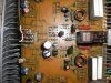
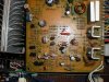
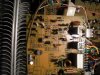
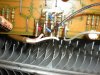
I pulled the amp board out and tested a few parts. Haven't found any bad parts yet. The previous owner has been messing around in here. As shown in the pictures, he cut the wirewrap, and soldered the end of the wire onto the post with a little drop of solder without even wrapping it around once. He replaced a few resistors. The second picture is two resistors he connected together. I pulled it out, and will grab a resistor from the lab at school tomorrow to replace it. I replaced a cap near pin 8 because the pin had been pulled out a bit. It was probably fine, but I haven't had it back together to test. I tested the relay driver transistors and a few near it, as well as a few near the resistor in picture 2.

Can I conclude from the fact that the hum is in both channels that it is an issue from the part of the board common to both channels?

I'm hoping I can finally have this thing up and running soon.
 

Attachments

  • DSCN1980.jpg
    DSCN1980.jpg
    120.1 KB · Views: 75
  • DSCN1978.jpg
    DSCN1978.jpg
    147.3 KB · Views: 74
  • DSCN1981.jpg
    DSCN1981.jpg
    122.2 KB · Views: 71
  • DSCN1979.jpg
    DSCN1979.jpg
    98.8 KB · Views: 61
  • DSCN1976.jpg
    DSCN1976.jpg
    101.9 KB · Views: 74
:yikes: I don't want to scare you.

First, the output transistors are unplugged at the sockets, then once the amps are in balance and the protection circuit behaving, the click after 5 to 7 seconds will indicate our first success.

test q131, q132, q133, q134 and indicate their polarity and part number
 
where are q131 and 132? I found q133 and 134 on the amp board, but the others aren't on the schematic or the parts list.

EDIT: do you mean q121, 122, 123, 124? I found those ones.
 
Last edited:
where are q131 and 132? I found q133 and 134 on the amp board, but the others aren't on the schematic or the parts list.

EDIT: do you mean q121, 122, 123, 124? I found those ones.

no that was for the 3800..... head up @@@, tired....

sx-3900 protection circuit:
q137, q138, q139, q140

q137, q138, q140 are npn

q139 can either be npn (old negative voltage circuit)
or pnp - (newer positive voltage circuit)
just checking for mismatch....

-16v means q139 is npn...

and with it (-16v being -5.2) being loaded down
What is left that could cause pin 4 voltage to be low? I checked all the transistors, resistors and diodes on the P/S board.
I suspect q139 (and maybe others) are bad :D *** on the AMPLIFIER board **** :D which is on the other side of the disconnected wire that allowed the voltage to increase.
also check/ strongly suggest replace Q125, q126 and replace c129 and c130 for potential shorts now or later.

since the ksc2310(150v) is on it's way out, the ksc1845(120v) or KSC2383(160v) will do.
 
Last edited:
I managed to toast 2 of the outputs (2SA1075), but I had spares from a 3800 parts unit. I'd replaced the caps, and put it back together, and plugged it in. An NPN driver is also gone, but not a dead short, there is still some resistance. I can't believe I didn't use the DBT. :sigh:

I also replaced the transistors mentioned in the previous post, which changed nothing.

Found a bad solder joint on pin 33 I'd missed previously. Looks like that connection took quite a bit of heat, the coating on the wire is melted.

I'm thinking it would be best to replace the rest of the transistors on the board.
What part should I use for the drivers?
Here is a draft of the parts list.
 

Attachments

original:
2sa985/a pnp to-220 bce 120v/150v 1.5a 25w 180mhz 35-320hfe orig 180mhz nsa driver
2sc2275/a npn to-220 bce 120v/150v 1.5a 25w 200mhz 35-320hfe orig 200mhz nsa driver


replacement:
757-2SA1930(Q,M) pnp to-220 bce 180v 2a 20w 200mhz 50-320hfe 200mhz nsa driver
757-2SC5171(Q,M) npn to-220 bce 180v 2a 20w 200mhz 50-320hfe 200mhz nsa driver

check every last resistor with one leg lifted

replace all diodes to be safe too.
 
Last edited:
I realize, at this point, that you are up to your ass in alligators, but would it not be a wise move to remove the ballasted light from near your equipment and eliminate the source of the hum? I don't care what kind of equipment you might have, but if you put a Tensor light, or similar type of light, near it, it will almost always create a hum.

I know at my work that a Tensor light that makes the rounds around the building has been caught causing a hum in both the building audio system, hearing impaired system and the headset intercom. It seems reasonably obvious to me that the light is either creating a source of RF interference that is somehow getting thru to your system; or injecting noise through the power line. This would have been the first thing I would have done. Unplugging the light and removing it as a possibility before going any farther. Just one man's opinion. :drool: :drool:
 
I realize, at this point, that you are up to your ass in alligators, but would it not be a wise move to remove the ballasted light from near your equipment and eliminate the source of the hum? I don't care what kind of equipment you might have, but if you put a Tensor light, or similar type of light, near it, it will almost always create a hum.

I know at my work that a Tensor light that makes the rounds around the building has been caught causing a hum in both the building audio system, hearing impaired system and the headset intercom. It seems reasonably obvious to me that the light is either creating a source of RF interference that is somehow getting thru to your system; or injecting noise through the power line. This would have been the first thing I would have done. Unplugging the light and removing it as a possibility before going any farther. Just one man's opinion. :drool: :drool:
The hum is present in the output whether the light is there or not.
 
Back
Top Bottom