
• The move to the new server is done. There are some software and database maintenance updates in process. This has us passing the hat around to help out. We appreciate any donations. Seriously, even a dollar helps. The payment page may be found here - https://www.audiokarma.org/support.html

Replacing a power transistor?

Mat86

Active Member
So I'm trying to restore a Pioneer RG-2 processor, despite being a novice, and picked up a broken unit. Fiddling around inside I found a power transistor to be rather loose, and applying pressure would bring the unit back to life.

The part is Q32 in the service manual, appears to be a Mitsubishi B682 (pictured in the attachment)

I assume this means replacing the transistor and not just soldering it in tighter, right?

How do I replace a part like this? I'm only familiar with caps right now...what's an equivalent to this part, do I get it on a place like Mouser/Digikey, and are there any other (non-electrolytic) parts (ie transistors) in here that I should be replacing while I've got it open?

edit: 2 posts after making this thread I've completely lost all power, not just power to 1 function (when I made this thread I still got the power LED on at all times)
 

Attachments
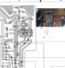
  • b682 transistor3.png
    b682 transistor3.png
    725.8 KB · Views: 72
Last edited:
Register to hide this ad
Very likely if it's "loose" the solder is cracked. Can't tell from that schematic snippet what it's doing, would have to be a very low power unit if that's an output transistor. Check for a broken trace too -- if that transistor got hot some time or other the pad at the lead can come loose from the board, and with heat cycles will crack the copper foil at the edge of the solder. Mechanical damage shows up like that too, I got a tuner once that was inert, had been banged hard in shipping and the transformer leads had popped the pads off the board and fractured the foil. Few seconds with a soldering iron and it's like new.

At any rate 5 seconds with a soldering iron -- NO POWER ON THE UNIT -- and it should be up and going. If it works when you press on it and makes contact there is nothing wrong with it.

How old is it? Less than twenty years, no point in doing anything else unless the sound is distorted or some other fault appears.
 
How old is it? Less than twenty years, no point in doing anything else unless the sound is distorted or some other fault appears.
43 years old, so wasnt sure if certain parts are end of life, to be safe

I'll give the solder a check as a stopgap solution for now, you're probably right, got worse in shipping at some point
 
Funny...moved it from my test bench to my work bench (it was running all day), then decided to test the sound one last time before taking off the front panel to clean some stuff and now it doesnt power on at all. All I did was move it. My easy project just got difficult...

the transistor in the original post only affected the processor / display, it still powered on and the tape light went on regardless if I applied pressure to it - and no amount of jimmying it right now is changing anything - does it sound like the transistor or something else just totally blew on me? i'm floored here
 
Last edited:
This is a common problem with Pioneer products. They ran the transistors hot with no heat sink or too small heat sink and too small pads on the board and they de-solder themselves. Look at the solder joints on that transistor. If you see a dark ring or a crack in the solder joints, resolder them with fresh solder. Should fix it.
 
If you can make it work by wiggling the transistor. It has a bad solder connection... Period !

that was the original problem (and yeah, popped the bottom open, no solder left), but now with no power at all I'm not sure if I wiggled myself off a cliff
 
So I removed, checked it, and re-installed it, unit still dead

Got to looking more into this, but, should the emitter register a certain amount higher than the collector? I only verified that E>C, but it was by a hair - does that mean my transistor is faulty and I need to yank it out again?
 
More depends on what the base voltage is. Depending whether its common collector or common emitter, expect the base voltage to be about a half volt different than either C or E. If its being used in a power supply, I'd figure collector goes to the supply rail, base goes to some reference voltage circuit, emitter is the output to wherever in the unit.
 
PNP and NPN transistors are mirror images, so emitter to collector voltage will be different depending on which one you have. What were you measuring and how? Voltage referenced to ground (black lead on ground, red lead on the pins -- one at a time,eh? No need to blow it up.

That transistor is what is usually referred to as a "pass transistor" -- it "passes" a voltage to the rest of the circuit based on a reference voltage, usually provided by a zener diode and a capacitor.

Poking around it with the power on is a bad idea, voltage spikes from poorly connected parts tend to fry other semiconductors.

Verify that the traces are not broken between the pad and the rest of the trace, that copper foil is very thin and easy to tear. Some manufacturer's used adhesive that won't hold up to repeated solder events, Yamaha being the worst I've come across, and it wouldn't surprise me that the heat that un-soldered that transistor lifted the pad off the board, and then the trace broke while you were poking it. The pad around the lead may look fine, and have a good solder joint, but if there is a crack between the pad and the rest of the trace, there is actually no connection at all!

Easy way to check is to set you DMM for resistance and put one lead on the let of the transistor on the component side of the board and check for continuity with the next component lead on the trace. If the trace is cracked it won't conduct. Component side, if you can reach every thing, works better than pushing down on the foil side as that often closes the crack while you are testing, and it opens up again when you stop pressing the lead down.

If you find a cracked trace, you can easily repair it by carefully scrapping the green resist coating off a portion of the trace next to the crack to expose clean copper, then bridge the crack with solder
 
What were you measuring and how? Voltage referenced to ground (black lead on ground, red lead on the pins -- one at a time,eh? No need to blow it up.

I only did a diode test (black to base, red to C/E) (when i removed it)

Is there another setting on the DMM I should verify?

Poking around it with the power on is a bad idea, voltage spikes from poorly connected parts tend to fry other semiconductors.

Noted :eek:

and it wouldn't surprise me that the heat that un-soldered that transistor lifted the pad off the board, and then the trace broke while you were poking it. The pad around the lead may look fine, and have a good solder joint, but if there is a crack between the pad and the rest of the trace, there is actually no connection at all!

This actually did happen! But I noticed it and made sure to connect to some exposed copper like you suggested when re-installing; checked from the pin to the rest of the trace and all showed the traces were intact
 
I have the same problem now on a Pioneer Dynamic Processor. The Transistor was completely loose. I removed it and cleaned up the board connection points and re-soldered it in and now I have a display. I turned it on for a bit but the Transistor got very warm. I am guessing it is shot but I will test it.
 

Attachments

  • !cid_CB53DD8C-B18C-4C3B-8398-955962ECBD43.jpg
    !cid_CB53DD8C-B18C-4C3B-8398-955962ECBD43.jpg
    91 KB · Views: 12
It may be OK but overheating because of some excessive load on the output side of it. Often thats a dying capacitor across the output but any sort of excess load will do it.

also possible it just runs hot by design and not enough heat sinking. If its that transistor in the first pic with no heat sink at all, that may be all it is. Adding a heat sink will cool it off.
 
I watched a couple of video on how to test a transistor with a digital multimeter with diode tester and tested my trans. According to Mouser it is a PNP with BCE leads and it tested bad.
 
Installed a new Transistor and two new switches for the tape monitor and for the Processor on off and all is working perfectly.
 
Back
Top Bottom