• Please note that Audiokarma will be offline briefly for updates early on Monday morning, September 28th.

Replacing cracked diodes ???

CavScout

Super Member
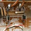
I am digging into an old receiver that had some smoke coming from a diode. Upon close inspection I found 2 of them were cracked.

I have never replaced a diode before so I am not sure how to size them.
The old ones were marked S 2 V 1

Is there some way to decipher that so I can find the right replacements ?
 

Attachments

  • 20180227_190013.jpg
    20180227_190013.jpg
    25.9 KB · Views: 64
  • 20180227_185755.jpg
    20180227_185755.jpg
    82.4 KB · Views: 63
  • 20180227_183117.jpg
    20180227_183117.jpg
    71.8 KB · Views: 62
Register to hide this ad
In a solid state receiver, it's likely 200 PIV will be enough. But 600 or 1000V will probably cost the same. And those might be 1A diodes, but 3-4A ones aren't much bigger or more expensive. The REAL issue is why they failed. Shorted cap or transistor or whatever probably. Gotta fix that first. Or you can just replace and watch the replacements smoke...
 
I thought maybe sometime before I got it someone maybe had a power surge. So do you think the new diodes will 100% start smoking ?
 
I thought maybe sometime before I got it someone maybe had a power surge.
Maybe, but unlikely.
So do you think the new diodes will 100% start smoking ?
Not necessarily, but likely.

Unless the diodes shorted out on their own, something drew a lot of current through those diodes. Typical candidates would be a shorted filter capacitor (less likely) or a shorted output transistor (more likely).
 
To identify those diodes I would find the service manual for your receiver. Look them up in the parts list and/or on the schematic (or both to verify that both places give the same information). Then come back here and ask for suitable replacement parts.
https://www.hifiengine.com/

All four, Q801 through Q804, should be replaced. They won't cost very much, shipping will probably be more than the new diodes. I would also purchase a lot of 10 as the per unit cost likely drops at quantity of 10. Then if issues persist, additional replacements would be at hand with no further shipping costs required.


It is possible that the cause of failure could be mechanical as opposed to electrical. The PCB does not show signs of overheating, and the diodes are physically broken. There could have been some flexing of the PCB, or the bend of the legs might have been off creating tension on the diode bodies for many years, etc. The pic with all four diodes still installed shows that one of the broken ones has pulled apart, suggesting that there was mechanical tension present.

If the failure was due to some kind of mechanical cause, then simply replacing them might be all that is necessary. Worth a try IMHO, especially if you order extras.

Prior to soldering in the new diodes, I would also re-flow the solder joints on those two pins, on the back side (the "solder side") of the board.

good luck with your project
 
Last edited:
And with a meter, check the capacitors and output transistors for shorts. Please don't guess as it has already been said that if you are not sure that these are indeed the problem, new one's will just go up in smoke.
 
Thanks for the advice.
How do I test for shorts in the capacitors ?
How do I test for shorts in the transistors?

I have a multimeter but I don't know what setting or where to put the red and black leads
 
3.15amp fuse .4 diodes ..mmmmmm .. 1 amp x4 will do i would think .

2 blown ones on negative supply so there is a clue . no telling yet if anything wrong on positive voltages yet .
 
Last edited:
My guess is this is a mechanical failure. Could someone please link to an example of a diode physically broken in the middle, like these, where the cause was due to electrical overload?

@CavScout If you are going to be working on any amp/receiver, the first step is to obtain the service manual. The manual will allow you to correctly ID those diodes and choose an appropriate replacement. Doing otherwise would be to rely on guesswork, and there is no need for that. Service Manuals for most units are available online for free. And those that are not can usually be had for $12 or so.
 
My guess is this is a mechanical failure. Could someone please link to an example of a diode physically broken in the middle, like these, where the cause was due to electrical overload?

@CavScout If you are going to be working on any amp/receiver, the first step is to obtain the service manual. The manual will allow you to correctly ID those diodes and choose an appropriate replacement. Doing otherwise would be to rely on guesswork, and there is no need for that. Service Manuals for most units are available online for free. And those that are not can usually be had for $12 or so.
both blown ? both same polarity in circuit . yes it is odd somehow .
 
One option is to replace the diodes then fire the unit up again only using a dim bulb tester. If theres a short that is killing the diodes - it will make the bulb glow brightly.

An issue like that with rectifier diodes in your AC/DC conversion stage seems unusual? Testing the powersupply caps for shorts should be straightforward.
 
I searched several free manual sites and was not able to find Marantz SR3100. Also did not find any data sheets, or references, for s2v1 diodes. But did find several references to s2v10 at datasheetarchive.com. s2v10 were rated 100V, 1.7A.

Assuming that s2v1 is the same as s2v10, and adding a bit for safety factor, something like 1n5402 (or 1n5403, 1n5404) might be a suitable replacement. Anyone else here have thoughts on that suggestion?

CavScout, I like pete's idea about looking at the main fuse. Its condition and whether it is or is not original, offer clues as to what might have happened.
 
Last edited:
I searched several free manual sites and was not able to find Marantz SR3100. Also did not find any data sheets, or references, for s2v1 diodes. But did find several references to s2v10 at datasheetarchive.com. s2v10 were rated 100V, 1.7A.

Assuming that s2v1 is the same as s2v10, and adding a bit for safety factor, something like 1n5402 (or 1n5403, 1n5404) might be a suitable replacement. Anyone else here have thoughts on that suggestion?

CavScout, I like pete's idea about looking at the main fuse. Its condition and whether it is or is not original, offer clues as to what might have happened.
S2V1 diodes do in fact cross reference to 1N5401....you can also use NTE5801, which are the same as both S2V1 AND 1N5401......but I agree with others.....check to see what caused them to fail in the first place so as not to blow up your new ones......
 
i just noticed there are or could be 2x 3.15 amps fuses for negative and positive supply . so my earlier estimate is incorrect . 3 amp diodes are more like it proved by the cross references .
 
Back
Top Bottom