javajunkie
New Member
Hello. Admittedly first time poster here asking for help, but have been cruising the site for some time for entertainment and the wealth of info.
I currently have the amp sitting on a 40W bulb current limiter for testing.
The amp mentioned above developed two shorted outputs - Q21 and Q23. I don't think the ones in place were original...they are the D587A and B617A sets, both channels. They apparently are slightly lower output and lower voltage handling. The amp had been operating correctly for some time prior to s**tting itself. I obtained and fitted replacements for Q21,23 which I tested prior to installation, and replaced various shorted transistors with same or subs as per a good thread I found on this site. All transistors were tested using my Peak DCA75. I have lifted and tested all resistors and electros on that half of the board. The caps have all been changed recently and are pretty new.
The problem is that I get a voltage reading of virtually zero when checking bias on both channels. By that I mean about .3 of a milliamp. This is by using the standard method outlined in the manual. I am well familiar with this meter, and have used it to adjust the bias on this amp before, as well as checking the bias on my tube guitar amps. I have checked and re checked Qs 7, 8, 9, 11, 13, 15, 17, 19, 26, 27, and electrolytics.
Transistors I replaced according to this info from another thread which had a happy ending:
http://audiokarma.org/forums/index.php?threads/ka-3500-transistor-subs.728835/
qe1-4 2sa620wn > ksa992fbu
qe5,6 2sc1885 > ksc2383yta
qe7,8 2sa620wb > ksa992fbu
qe9,10 2sa733 > ksa733cyta
qe11-14 2sc945 > ksc945cyta
qe15,16 2sa733 > ksa733cyta
qe17,18 2sc1735 > ksc2690ays
qe19,20 2sa850 > ksa1220ays
qe25, 27 2sa673 > ksa1220ays
qe26 2sc1222 > ksc1845
Some test results for your perusal:
E C B
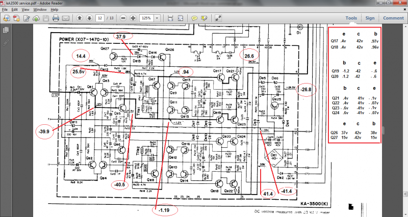
Q17 .43 38 .97
Q18 .42 38 .97
Q19 - .6 -38 -1.2
B C E
Q20 -1.2 -38 - .6
Q21 .43 38 - .1
Q23 - .63 -38 - .1
Most of my readings seem to be there or abouts. My reading at the nodes of R17,19 and 18,20 is only 24.2vdc where 26 is specified.
I have checked the .47ohm resistors for continuity.
Any help greatly appreciated, I'm fine with tubes but still coming up to speed with solid state. I can provide plenty more readings/measurements as req'd.
Cheers!
P.S. I think there may be a discrepancy with the pin arrangements of Q17,18 but will wait to hear anything before getting into it.
I currently have the amp sitting on a 40W bulb current limiter for testing.
The amp mentioned above developed two shorted outputs - Q21 and Q23. I don't think the ones in place were original...they are the D587A and B617A sets, both channels. They apparently are slightly lower output and lower voltage handling. The amp had been operating correctly for some time prior to s**tting itself. I obtained and fitted replacements for Q21,23 which I tested prior to installation, and replaced various shorted transistors with same or subs as per a good thread I found on this site. All transistors were tested using my Peak DCA75. I have lifted and tested all resistors and electros on that half of the board. The caps have all been changed recently and are pretty new.
The problem is that I get a voltage reading of virtually zero when checking bias on both channels. By that I mean about .3 of a milliamp. This is by using the standard method outlined in the manual. I am well familiar with this meter, and have used it to adjust the bias on this amp before, as well as checking the bias on my tube guitar amps. I have checked and re checked Qs 7, 8, 9, 11, 13, 15, 17, 19, 26, 27, and electrolytics.
Transistors I replaced according to this info from another thread which had a happy ending:
http://audiokarma.org/forums/index.php?threads/ka-3500-transistor-subs.728835/
qe1-4 2sa620wn > ksa992fbu
qe5,6 2sc1885 > ksc2383yta
qe7,8 2sa620wb > ksa992fbu
qe9,10 2sa733 > ksa733cyta
qe11-14 2sc945 > ksc945cyta
qe15,16 2sa733 > ksa733cyta
qe17,18 2sc1735 > ksc2690ays
qe19,20 2sa850 > ksa1220ays
qe25, 27 2sa673 > ksa1220ays
qe26 2sc1222 > ksc1845
Some test results for your perusal:
E C B
Q17 .43 38 .97
Q18 .42 38 .97
Q19 - .6 -38 -1.2
B C E
Q20 -1.2 -38 - .6
Q21 .43 38 - .1
Q23 - .63 -38 - .1
Most of my readings seem to be there or abouts. My reading at the nodes of R17,19 and 18,20 is only 24.2vdc where 26 is specified.
I have checked the .47ohm resistors for continuity.
Any help greatly appreciated, I'm fine with tubes but still coming up to speed with solid state. I can provide plenty more readings/measurements as req'd.
Cheers!
P.S. I think there may be a discrepancy with the pin arrangements of Q17,18 but will wait to hear anything before getting into it.
Last edited: