• The move to the new server is done. There are some software and database maintenance updates in process. This has us passing the hat around to help out. We appreciate any donations. Seriously, even a dollar helps. The payment page may be found here - https://www.audiokarma.org/support.html

Resistors. How to determine voltage and other spec.

Hifibythekg

Super Member
Need to replace some resistors on aYamaha A-1 amp. The Service Manual simply says they’re “Carbon 330ohms” but when ordering additional specs are offered such as:
-power rating?
-resistance tolerance?
-voltage rating?
Can anyone advise what I should be seeking for each of the above. (And how does one go about deducing this?)
Additionally, in this location are carbon still preferable to metal oxide, or metal film?
Location:
Electrolytic Capacitor Board:
R 101,102, 103, 104.
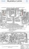
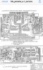
Will try to provide a screenshot of the pcb and schematic.
 
Register to hide this ad
Typically SS stereo components mostly use 1/4 watt resistors. Tube electronics typically use 1/2 watt and higher depending on it's use. You used to be able to tell by the physical size of the resistor but I've recently built tube amps that have 1/2 watt resistors the same size as 1/4 watt resistors.
A resistor's tolerance is given by the last color band of it's value code. Carbon comp and film resistors have a 10% (silver) or 5% (gold) tolerance. Metal film resistors with a 1% rating use a brown color band. There are other color codes for tolerance but these are what you will typically see.
The voltage rating is given on the part's datasheet. As far as I know there is no way of telling by simply looking at the resistor. If memory serves 300 to 350 volt resistors are used most in SS electronics.
I typically use metal film resistors in all my builds and re-builds. These are typically in the signal path. I use metal oxide and/or wire wound power resistors where needed.
 
Hey Stephen, thank you for taking the time to pen a fulsome explanation.
Much appreciated.
Just a thought, typically is a lower figure for resistance ‘better‘?
Where my intended replacement resistors are located it would seem that I should source some that are:
metal film, 1% tolerance, 1/4 watt, 300-350 V, 330 ohm
Have I got this right?
 
"Lower figure" of what? Resistor tolerance? If so then yes, a lower tolerance number is better. The lower the percentage number the tighter the tolerance. If you can measure a voltage across your 330Ω you can use Ohm's law to calculate the amount of power dissipated by the resistor.

Ohm's law is V = I x R
V = Voltage
I = Current in amps
R = Resistance in ohms

In your case R = 330Ω. You would then measure the DC voltage across it with a DMM. Lets say there is 5V being dropped across the resistor.
To determine the amount of current you would use the formula I = V/R or I = 5V/330Ω which equals .015 amps or 15ma.

To calculate Power you use the formula P = I x V
P = Power in watts
P = .015 amps x 5V
P = .075 Watts This is well below the limit for a 1/4W (.250W) resistor.
 
Resistors don't usually go bad unless something else in the circuit is causing too much current draw.

Are the said resistors burn't up or open?

Either/or............something else is probably amiss. :idea:
 
Voltage rating of resistors used in audio is determined by the wattage rating & ohms value of the resistor, because voltages are relatively low in most audio settings. In industrial applications where very high (many meg-ohms) value resistors are used, currents may be so small that wattage is not a concern, but the voltage drop across the resistor can be high, causing possible arc-over of trim kerfs.
 
Agree with making sure there isn't some other problem first. Resistors rarely go bad unless overloaded.

They can be worked too close to their ratings for a very long time and be a little bit toasty looking though. If thats the case, maybe consider bumping the wattage. Using a higher watt resistor won't bother anything, and if its gotten warm enough to tan the board, maybe consider leaving the legs a bit long so there is air space between the resistor body and the circuit board for cooling.

Generally there is a statement somewhere on the schematic or service manual about "resistors are all X wattage unless otherwise noted". Have a peek around. 1/4 for solid state is a reasonable assumption though.
 
Cademan, Eggelings and Gadget73.
Thank you for the very helpful advice. Am making good progress now, and this advice will help me along.
 
Back
Top Bottom