• The move to the new server is done. There are some software and database maintenance updates in process. This has us passing the hat around to help out. We appreciate any donations. Seriously, even a dollar helps. The payment page may be found here - https://www.audiokarma.org/support.html

Restomod Dynaco Stereo 120 — high DC offset

TXGardener

New Member
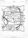
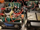
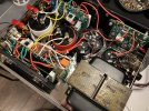
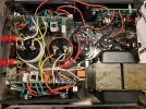
I am rebuilding a Dynaco Stereo 120, with UpdateMyDynaco power supply and replacement caps, and the eBay TIP-mod amplifier boards, and I am seeing two issues that I could use some help with. 1) High DC offset (~200mV), and 2) the #4 and #14 eyelets are reading 71.3V instead of 36 and 37V, respectively. I measure 34.09V across R C7 and 34.12V across L C7. Just about every piece is new, and Q5 and Q6 are 2N3055s. Is there an obvious place to start troubleshooting the DC offset? Is a ~200mV DC offset even a problem on a TIP-modded Stereo 120? Thanks in advance.
 

Attachments

  • IMG_0470.jpeg
    IMG_0470.jpeg
    101.5 KB · Views: 22
  • IMG_0469.png
    IMG_0469.png
    493.9 KB · Views: 20
  • IMG_0471.jpeg
    IMG_0471.jpeg
    86.5 KB · Views: 23
  • IMG_0468.jpeg
    IMG_0468.jpeg
    173.2 KB · Views: 23
  • IMG_0467.jpeg
    IMG_0467.jpeg
    195.7 KB · Views: 18
  • IMG_0466.jpeg
    IMG_0466.jpeg
    193.5 KB · Views: 22
Register to hide this ad
1) Cap coupled amps usually don't have an adjustment for DC offset, and you may need to connect an 8 ohm dummy load (or speaker you don't care about) to get a realistic number.

2) Which board, left or right? Just noticed that the test points are different on the schematics, right versus left. Also what is on #7/#8 on both boards? It should be approx. 1/2 of the 72 volt supply.

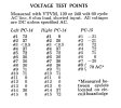
Use your Test Points picture and write down every voltage for the left and right boards. Maybe it will make more sense.
 
Thanks for responding, @TPettenati. Seems like maybe I jumped the gun a little. The instructions did say that measurements should be taken with the inputs shorted and an 8 ohm load on the outputs (speakers). Well, I followed the instructions, and here are the measurements. Looks like the DC offset is actually quite low (3mV on eyelet 11), so I hooked it up to my A-25s and it sounds pretty sweet.

I am still concerned about point 2 on the left and point 14 on the right running about twice as high as they should be, but everything else seems right on the money. ¯\(ツ)

Spec (V)Left PC-14 (V)Right PC-14 (V)
01. 72/071.30
02. 37/3671.334.31
03. <0.500
04. 3771.371.3
05. 7271.371.3
06. 3635.0335
07. 3634.434.32
08. 3634.434.32
09. 7170.670.6
10. 7170.670.6
11. 00.0030.003
12. 000
13. 000
14. 36/3734.3571.3
15. 0/720.00171.3
 
Last edited:
#4 on both boards is wrong. Looks as if the path from #4 through Q4 is open. The path is #4 thru R28 to Q4-E to Q4-C thru R14 to ground. Check to see if Q4 is the correct transistor and installed correctly, or possible blown.
 
I checked and rechecked Q4, and there were both installed properly. Then I looked at the wire connection points again, and that's where I discovered my issue. It turns out that the wires at #4 on both amps were not fully soldered to the back of the PCBs. So, I slathered both sides of the connection point with solder to make sure that the wires were 100% making contact, and...#4 is now reading 36.3 on both channels! Thanks for taking the time to help me. I appreciate it.
 
Back
Top Bottom