• The move to the new server is done. There are some software and database maintenance updates in process. This has us passing the hat around to help out. We appreciate any donations. Seriously, even a dollar helps. The payment page may be found here - https://www.audiokarma.org/support.html

Restoring / recapping a Yamaha M-4 amplifier in 2026

rupes2

AK Subscriber
Subscriber
I bought a functional Yamaha M-4 that I wanted to restore / recap. First up was recapping the power supply and replacing both relays. As it gets harder to source some capacitors it seems to take a while to build a list of parts to order and where to source them. Sharing this in case it is useful to someone.

Capacitors for power supply

CapacitorValueLS (pcb)Replacement Part #NotesSource
C6091000µF, 25V8mmUHE1V102MHD635VDigiKey
C613, C614100µF, 100V8mmUPW2C101MHD1TN160VMouser
C615100µF, 25V5mmUPW1J101MPD63VDigiKey
C61647µF, 16V4mmUPW1J470MPD63VDigiKey
C60810µF, 25V4mmUKL1V100KDD1TA35V, 10%Mouser
C610, C611, C62310µF, 16V4mmUKL1V100KDD1TA35V, 10%Mouser
C61910µF, 50V, BP5mmUEP2A100MPD1TD100VDigiKey
C6182.2µF, 25V, BP4mmUEP1H2R2MDD50VMouser
C621, C6220.68µF, 50V4mmMKS0C036800F00KC0063V Wima filmMouser
C617, C6200.1µF, 50V4mmMKS0C031000C00KI0063V Wima filmMouser

Capacitors that were more than 20% outside their nominal capacitance value (measured with a GM328 meter):
  1. C610 / C611 (10µF) -> 12.7µF (+27%) / 12.59µF (+26%). Part of the 12V regulated power supply circuit.
  2. C621 / C622 (0.68µF) -> 0.862µF (+27%) / 0.867µF (+28%). Part of the LED power meter circuit.
  3. C617 / C620 (0.1µF) -> 0.256µF (+156%) / 0.210µF (+110%). Part of the LED power meter overload circuit.
I did not replace the trimmers for the LED meters as Bourns part# 3386G-1-152LF was not available.
 
Last edited:
Register to hide this ad
Filter capacitors

Original specs:
Nichicon CE 15,000µF, 75WV, 85°C, 50mm diameter, 90mm length, 4.5mm wide solder lugs that are 18mm apart.

When it came to selecting the filter capacitors the two best options I could find were:
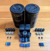
  1. Cornell Dubilier 383LX223M080B092VS. 22,000µF. Rated for 3000 Hrs @ 105°C so should last a long time. Almost exactly the same size as the originals (2mm taller). 5 pin snap-in so for each cap you have to cut off 3 pins and drill 2 holes in the PCB.
  2. Nichicon KG Gold Tune LKG1K153MKZ. 15,000µF. Audio grade. 8mm taller than the originals. Has solder lugs like the originals that will fit after making them narrower. These were discontinued around 2023 and are hard to find.
I went with the Cornell Dubilier caps. They are not an audio grade capacitor, but neither were the original filter caps, and the specs are better than the originals.

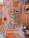
I was a bit anxious about drilling the PCB especially since I could not find any photos online. I had AI create me a template PDF (attached) that really helped with marking up the PCB. Drilling the four 2mm holes was straightforward. I have attached photos showing where the 4 holes end up on the PCB.
 

Attachments

  • m4_383lx_layout.pdf
    m4_383lx_layout.pdf
    3.3 KB · Views: 9
  • pcb_bottom.jpg
    pcb_bottom.jpg
    152.8 KB · Views: 15
  • pcb_top.jpg
    pcb_top.jpg
    246.2 KB · Views: 15
Last edited:
Relays

The replacements for the orginal DEC Type MS4U relays are the Omron MY4-02-DC12.

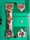
These relays have 4 contacts. The original relays have the contacts tied together internally in pairs so each connection is switched with 2 contacts. You can just remove the 6 unneeded pins and use the Omron relays as is but then each connection is only switched with 1 contact.

I had seen this post where this was addressed by drilling 2 holes in the PCB and then removing the other 4 unneeded pins. Once mounted 2 jumper wires are attached under the PCB. Instead I popped the cover of each relay and added 2 jumper wires internally to make the relay functionally equivalent to the original (see attached). If you are going to do this I suggest you remove most of the solder that is there first as I believe it is lead-free. I then removed the 6 unneeded pins.
 

Attachments

  • relay_modification.jpg
    relay_modification.jpg
    150.5 KB · Views: 20
Last edited:
The amp is back up and running and I adjusted the amp module trimmers using this guide.

Still to do:
- Recap the amp modules (+ replace trimmers and 2SC458 transistors)
- Upgrade the speaker terminals
- Replace the button lamps
 
Last edited:
Components for Pre Drive Sheet (left)

ComponentValueReplacement Part #NotesSource
C225100µF, 10VUPW1H101MPD50VDigiKey
C203, C205, C217, C21910µF, 80VUKL2A100KPD1TD100VDigiKey
C2311µF, 100VMKS2D041001K00JSSD100V Wima filmMouser
TR227, TR2292SC458CKSC1815YTASame pinoutDigiKey
VR201100Ω3296P-1-101LFmulti-turn, DC balanceDigiKey
VR2032.2KΩ3296P-1-202LFmulti-turn 2KΩ, 65V adjDigiKey

Both Pre Drive sheets completed

On the right board FR202 had been replaced with a regular resistor and FR204 measured 42.2 ohm (+27.9%). I could not find fuse resistors so replaced them with 0.25W metal film resistors with flame retardant coating (part # RNMF14FTC33R0).
 
Last edited:
Components for Drive Sheet (left)

ComponentValueReplacement Part #NotesSource
VR4014.7KΩ3296P-1-502LFmulti-turn 5KΩ, BiasDigiKey
C40110µF, 16VRFS-25V100MF3#525V Elna Audio SILMIC IIMouser

Both Drive sheets completed
 
The recap is complete. 31 electrolytic capacitors, 6 trimmers, 4 transistors, and 2 relays.

Cost of the capacitors, trimmers, transistors, relays, and mica thermal pads in 2026 was about $140 (without shipping and tax).
 

Attachments

  • m4.jpg
    m4.jpg
    162.1 KB · Views: 29
Speaker terminals

I was looking for speaker terminals that matched the aesthetic of the M-4 and were good quality. I saw listings on EBay that were made of a zinc alloy or did not specify what they were made of.

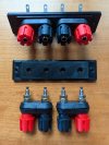
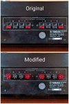
In the end I went with the Mueller 6883 from Digikey (same as the Pomona 6883). The other thing I like about these is they are keyed into the plastic piece that holds them together in pairs. So it is not necessary for the adapter plate to be keyed. Someone created a 3D printed adapter plate that works perfectly with these. I also ordered some Keystone Electronics 7340 solder terminal lugs. Total cost was about $20 (without shipping and tax). I am happy with the result.
 

Attachments

  • m4_6883.jpg
    m4_6883.jpg
    178.3 KB · Views: 41
  • m4_speaker_terminals.jpg
    m4_speaker_terminals.jpg
    144.4 KB · Views: 23
Last edited:
Button lamps

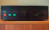
Since the lit buttons are an important part of the look of this amp I decided to go with incandescent lamps (14.5v, 80mA, 4mm). If I still have the M4 when they die I will try LEDs next time.

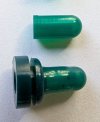
The orange silicone boot for the power switch was missing and I only had one good green silicone boot for the speaker buttons. I got replacement lamps and silicone boots from @dgwojo who was great to deal with. The dark green boots he has match the color of the originals. I don't have the an original boot to compare the orange to but based on brochure images the power button might be a bit too orange (the original was more amber?) but it looks good. I got some grommets from the hardware store to use with the new boots and that worked well.

This was a fun amp to work on. My FB marketplace ban did not last and I think a tube amp project will be next.
 

Attachments

  • m4_front.jpg
    m4_front.jpg
    100.2 KB · Views: 12
  • m4_lamp_boots.jpg
    m4_lamp_boots.jpg
    113.4 KB · Views: 13
  • m4_nudie.jpg
    m4_nudie.jpg
    205.3 KB · Views: 13
Last edited:
Back
Top Bottom