sKiZo
Hates received: 92644 43.20°N 85.50°W
Beauty!
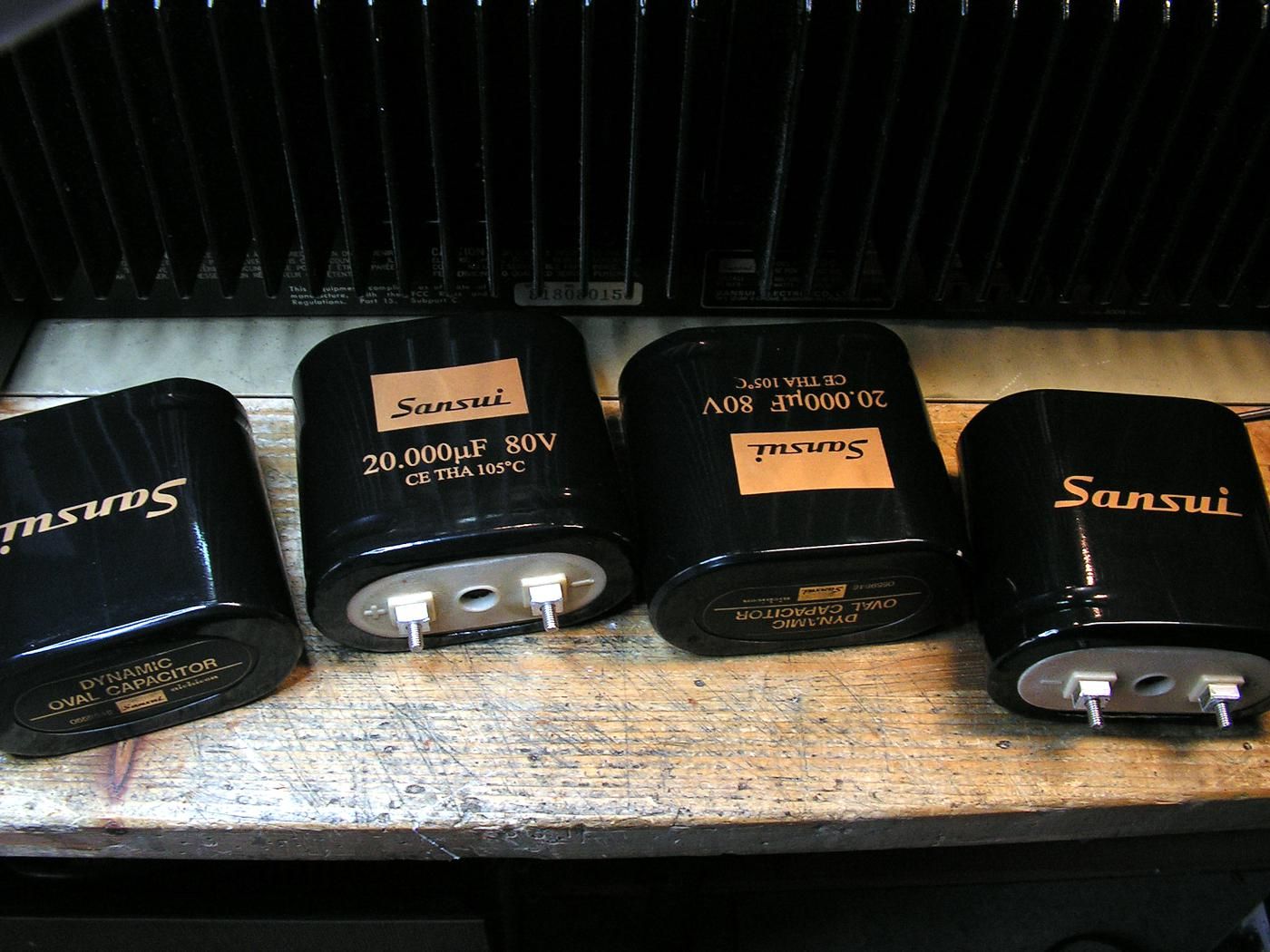
Certainly something to be said about the seamless look, but wondering if instead of having the labels professionally printed (which I expect cost dearly for a low production run), you could just print them yourself on photo grade paper and stick them to the new heat shrink? I did something kinda sorta similar on a recent project ... those would be the white PIO's on the circuit board ...
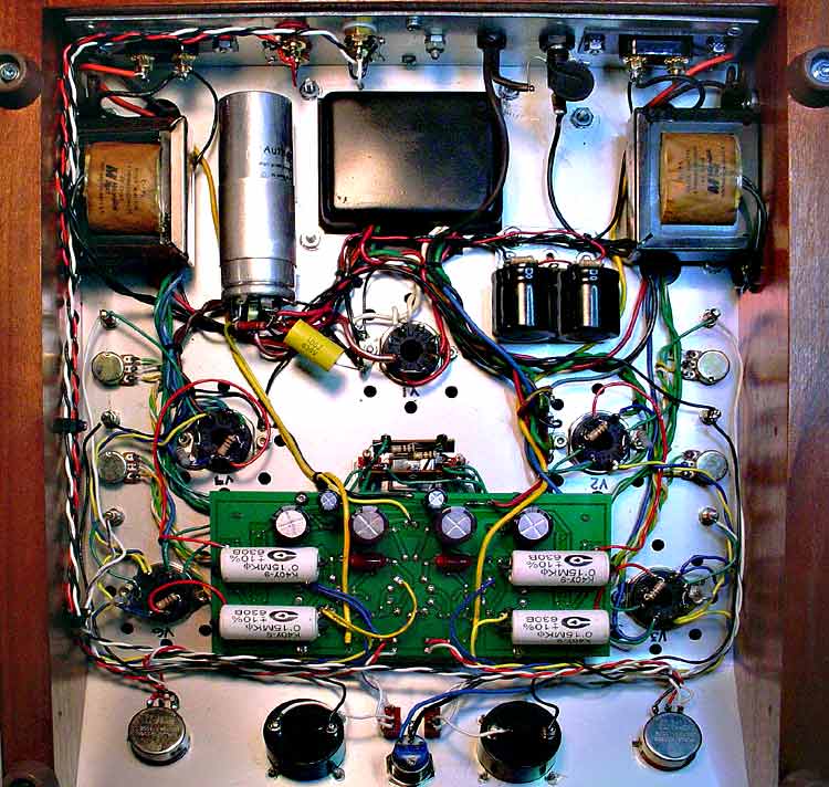
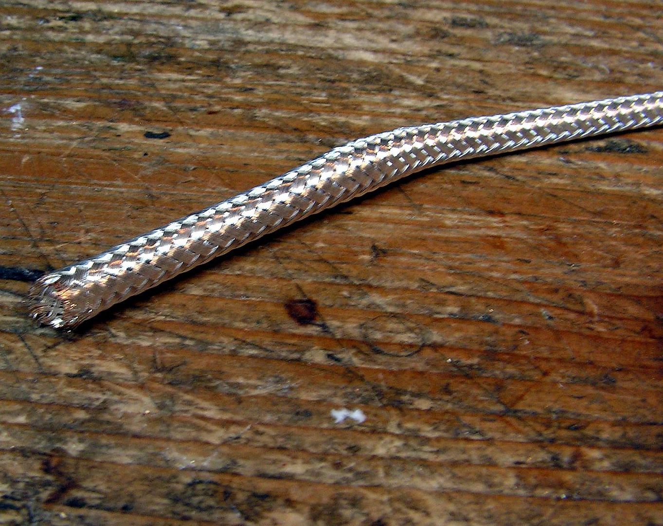
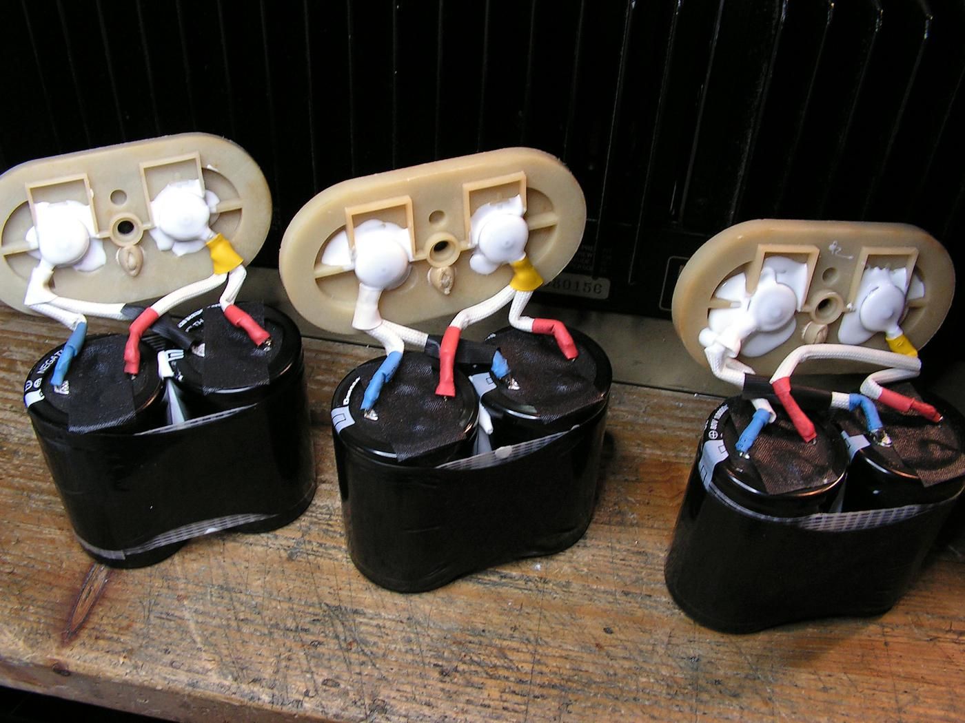
Also wondering about the twisted leads. Any purpose other than increasing the effective gauge of the wire?
Certainly something to be said about the seamless look, but wondering if instead of having the labels professionally printed (which I expect cost dearly for a low production run), you could just print them yourself on photo grade paper and stick them to the new heat shrink? I did something kinda sorta similar on a recent project ... those would be the white PIO's on the circuit board ...
Also wondering about the twisted leads. Any purpose other than increasing the effective gauge of the wire?
Last edited: