• The move to the new server is done. There are some software and database maintenance updates in process. This has us passing the hat around to help out. We appreciate any donations. Seriously, even a dollar helps. The payment page may be found here - https://www.audiokarma.org/support.html

Restoring the AU-D907G Extra

wmac

AK Subscriber
Subscriber
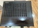
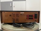
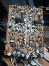
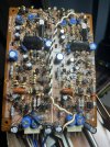
The amplifier arrived operational but exhibited intermittent noise from oxidized controls. All switches and potentiometers were thoroughly cleaned and treated, after which the issue was completely resolved. The amplifier will then be fully restored as a preventive measure for long-term reliability.

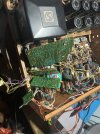
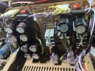
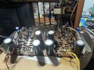
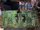
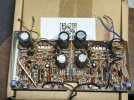
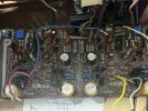
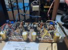
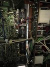
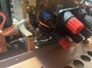
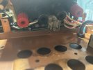
Bellow the picture of it:

IMG_1453.jpg

IMG_1461.jpg

IMG_1456.jpg
 
Register to hide this ad
It has a rare technical quirk or let's say trivia.

It mates the Super Feed Forward with floating ground design which later matured into x balanced amplifier line.
 
Yes, you are right just
It has a rare technical quirk or let's say trivia.

It mates the Super Feed Forward with floating ground design which later matured into x balanced amplifier line.
finished restoring an X1. The big issue with this one is accessing the boards; I will have to disassemble everything. :mad: :mad: :mad:
 
Finished working on the drivers and outputs for F-3679 as pic below:

IMG_2721.jpg

Now start to work on the power supply F-3673; here is where the fun starts. I have to work for 2 days to remove all the glue and check all components that were affected by it :mad: :mad: :mad:


IMG_2722.jpg
 
Work on the glue is boring so I decided to start and then I went to service the tone board and the speaker selectoras picutres shows.

IMG_2727.jpg

IMG_2728.jpg


This is where I am at the power supply board, half is done and other half I still have to clean :mad: :mad: :mad: :mad:

IMG_2732[1].jpg
 
Working on the Power amp board F-3678

IMG_2756.jpg

The styro capacitors were removed, and all of them were tested open; they were replaced with PP Film caps 1000pF 160V

IMG_2757.jpg

There was that nasty glue everywhere.

IMG_2759.jpg


All Zener diodes were damaged by the glue corrosion.


IMG_2760.jpg

Took me 2 days to clean this board; once I had to replace some components that were contaminated by the glue, remove most of the others, clean, test, and reinstall. The board is now cleaned:

IMG_2764.jpg

F-3678 board is restored, new caps and zeners replaced, and now I am reflowing the solder and cleaning the back.

IMG_2765.jpg

IMG_2768.jpg

Finishing this, it is time to reinstall the board in place and start the calibration :) :) :)
 
Finishing with the F-3679, waiting for the delivery of the polish paste to clean the RCAs and mount everything back to start calibrations and tests.IMG_2797.jpgIMG_2798.jpg
 
These are the boards and capacitor series and brands that were replaced:

Board / PositionOriginalReplacement
F-3677 EQ100 µF / 25 V NichiconVishay MAL214651101E3, 100 µF / 50 V
F-3677 C25/C2647 µF / 10 V NichiconRubycon YXF, 47 µF / 50 V
F-3677 C2110 µF / 50 VRubycon YXF, 10 µF / 100 V
F-3677 C5/C8 factory-mod positions10 µF / 25 V Nichicon SLRubycon YXF, 10 µF / 100 V
F-3677220 µF / 35 V ElnaElna RJH, 220 µF / 35 V
F-3677100 µF / 35 V NCCVishay MAL214651101E3, 100 µF / 50 V
F-3678 power amp470 µF / 100 V Elna “For Audio”Nichicon UFW, 470 µF / 100 V
F-3678 C23470 µF / 50 VPanasonic EEU-FM, 470 µF / 50 V
F-3678 parallel bypass10 nF styreneVishay MKP1837, 10 nF polypropylene
F-3678 C3 / similar1 nF styreneWIMA FKS2, 1 nF / 100 V polypropylene/film replacement actually fitted*
Regulated PSU1000 µF / 63 V NichiconRubycon PX, 1000 µF / 100 V
Regulated PSU470 µF / 50 V Elna AWDNichicon PW, 470 µF / 100 V
Regulated PSU220 µF / 16 VElna RJH, 220 µF / 35 V
F-3679 protection220 µF / 16 V NichiconElna RJH, 220 µF / 35 V
F-36791 µF / 50 V polarized electrolytic1 µF / 100 V WIMA polypropylene film
F-3679100 µF / 6.3 V Nichicon NPElna BP / RSRBD, 100 µF / 50 V bipolar
 
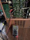
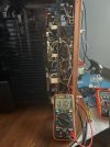
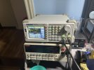
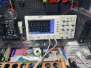
Starting the tests:
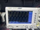
First, I'll see if I have any phase issues:
Load is 8 ohms, 100 W

IMG_2812.jpg

Change to a square wave, still with an 8-ohm load. Configuration: 1 kHz, 500mV VPP

IMG_2813.jpg

IMG_2814.jpg

Then 10 kHz at the same amplitude

IMG_2816.jpg

IMG_2815.jpg

At 20 kHz


IMG_2818.jpg

IMG_2817.jpg


For the stress and clipping test, I changed the load to 4 ohms, 200W. I could not clip because I had the input at 500mV VPP, but I was satisfied that at full volume I got 68.75 VPP, which is about 148 W. This amp was specified at 130W, so I did not change the input Voltage.

IMG_2819.jpg


Then the THD for the same setup with a 4-ohm load:

Measured per channel, at full volume:

IMG_2825.jpg

The other channel:

IMG_2826.jpg

Now I am going to close the box and listen for a week, and measure the temperature.
 
:rockon: bravo!!

Why were the styro caps dead? Do we know the cause of damage? Glue?
The big styros were open, and I had an accident with the small one, removing the glue, so I replaced both to match the channels with PP film caps.
 
Back
Top Bottom