
• The move to the new server is done. There are some software and database maintenance updates in process. This has us passing the hat around to help out. We appreciate any donations. Seriously, even a dollar helps. The payment page may be found here - https://www.audiokarma.org/support.html

Reviving a Nakamichi TA-3A

jjbunn

Member
This TA-3A has no sound: it doesn't come out of protection - power up shows an amber led then shortly after a green flashing led.

Having read lots of material on this forum about the TA-3 I started off by replacing R309L and R309R - the existing 22kOhm resistors were different wattage, so maybe someone has been inside this amp before me, although you wouldn't guess it judging by all the dust! The lower wattage R309R measured a bit high. But I replaced them both with 2W types.

I also found an unsoldered capacitor leg nearby to R309L, so I soldered it.

No change on power up.

Then I removed all the connectors to the logic board. In that state, the amp powered up to solid green led. I replaced all the connectors one by one until the amp wouldn't power up properly.

It turned out that CN 1 was the cause: with it disconnected the unit powers up to solid green led. But there is still no sound from speakers or headphones. My understanding is that CN 1 is related to auto power control, but I'm not sure.

I checked the onboard battery, and it is essentially dead, so I have a replacement on hand, just waiting for the socket to come in (I'm not going to try soldering to the battery itself).

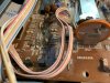
I spotted something odd on the logic board - see photo attached. It's CN 12, which seems to have had a wire soldered between the pins, which is now broken/disconnected. Should CN 12 pins be shorted together?

Thanks for any advice/tips/suggestions!2021-02-25 18.13.36.jpg
 
Register to hide this ad
I have done work on my TA-2A with help from people and threads on this site .Someone will be of better assistance than me however in the mean time check all the areas the pcb has darkened for solder joints and especially the relay pins.That spot you pictured maybe a test spot for bias adjust so leave unattached for now. Hope this is of help...cheers
 
It would be prudent to check the voltages on the Power Supply board. These voltages and where they go to on the Logic Board seem to dictate a lot of what happens during the startup sequence, and a lot of that is controlled by the large IC (U503). The TA-2A and TA-3A share much circuitry, and this seems to be particularly true for the PS (a quick look indicates all components even have the same numbers).

A listing of what the voltages on CN-9 on the PS board on a TA-2A should be are given in post #7 of this thread: http://audiokarma.org/forums/index.php?threads/nakamichi-ta-2a-power-supply-board.767305/

Aside from this, it would be worthwhile checking if there is power to the speaker relay. It is also fairly common to find that some cold solder joints have developed on the relay pins, so reflowing those is also prudent if the relay is not working.

In post 26, Mannegizen gives a list of what most of the connectors control on the Logic Board. He gives CN-1 as "Power of muting circuit", which might mean "Power off muting circuit", so that circuit could be playing a role in your symptoms. There is a lot of other info in that thread that might be of help in troubleshooting start up issues.

I can't help on the CN-12 business; the TA-2A does not have that. What you have does look quite odd, though.
 
I should also mention that there is an service addendum (last page of the SM on hifiengine) on two transistors on the Main Board. These are part of the +/-18V circuit (not generated on the PS board), and tend to run warm. There are a few posts about these on TA-2/3s; some have added heat spreaders to them. The 18V supply is used on several ICs, such as those that control speaker switching (U204, U206) on the Main Board. In light of this, you should check that you have a proper voltage for the +/-18V supply.
 
I should also mention that there is an service addendum (last page of the SM on hifiengine) on two transistors on the Main Board. These are part of the +/-18V circuit (not generated on the PS board), and tend to run warm. There are a few posts about these on TA-2/3s; some have added heat spreaders to them. The 18V supply is used on several ICs, such as those that control speaker switching (U204, U206) on the Main Board. In light of this, you should check that you have a proper voltage for the +/-18V supply.

Excellent advice, thanks. Right now I am about to replace the onboard battery. I also found that the speaker relay was not behaving reliably, even after some squirts of DeOxit and activating it on the bench supply many times, so I have a replacement on order.

I did check the voltages on CN-9 on the power supply board, and they look good. I'll now take a look at the 18V supply as you suggest. The deeper I dive, the more convinced I am that someone else has been working on the unit before me: e.g. the relay had melt marks on its case where it had been touched by a soldering iron :-(
 
Welcome aboard JJ.. That B501 battery is for your preset memory .. Consider replacing it once you get this Nak up and running.
 
OK, battery replaced, and speaker relay removed waiting for a replacement.

In this mode, the amp powers up to solid green.

I've been making some measurements of the voltages on Q206-Q211, and this has revealed that there is something wrong on the Q209/210/211 side, as they don't measure what they should:

Q211 base -32V (should be -19.4)
Q210 ditto
Q209 collector +53V (should be +36V)

... the plot thickens :-)
 
Mannegizen's comment in this post https://audiokarma.org/forums/index...ichi-ta-3a-project.732531/page-2#post-9932414 may be relevant:

A failed transistor, either Q208 or Q209, in the +/-18V regulator circuit can give you around 35 volts or so on either the positive or negative rail.
The unit will still work, but a resistor or two will be fried on the tone boards +/-12V regulation circuit.

The zeners in the 18V circuit bear checking as well. The whole area does seem to get warm, as a lot of voltage is being dropped to get down to the regulated +/-18V.
 
Mannegizen's comment in this post https://audiokarma.org/forums/index...ichi-ta-3a-project.732531/page-2#post-9932414 may be relevant:


The zeners in the 18V circuit bear checking as well. The whole area does seem to get warm, as a lot of voltage is being dropped to get down to the regulated +/-18V.

Useful - thanks! I think either Q209 is dead or the associated Zener, but I need to check more. There is evidence things have got hot around that area, as you say. Wires in the region are somewhat blackened. I wonder whether it's worth attaching heatsinks to those transistors? Also, I will need to take a look at the tone board, but first I'll try to fix the 18V supply.
 
It probably is worthwhile attaching heat spreaders. I've done this on the slightly older SR-series Nak receivers, where the larger TO-220 transistors on the 18V circuit seemed to get even hotter.

Even though this link is for a TA-2A, the issue is the same and the +/-18V circuit is nearly the same. Just note that the component numbers are shifted/different (e.g., Q209 on one does not correspond to Q209 on the other), so you will have to compare the same area in the TA-2A and TA-3A schematics to know which ones Pete B is referring to. Also note that Pete B initially thought one of the transistors had a higher power rating (625mW) than it actually has (250mW) (see posts following the one this link takes you to).
https://audiokarma.org/forums/index...-2a-considering-a-recap.894710/#post-13355261

Also, in following posts in that thread, Pete B makes some suggestions on possible substitute transistors, and gives a link to some slip-on heat spreaders for TO-92 devices.
 
It probably is worthwhile attaching heat spreaders. I've done this on the slightly older SR-series Nak receivers, where the larger TO-220 transistors on the 18V circuit seemed to get even hotter.

Even though this link is for a TA-2A, the issue is the same and the +/-18V circuit is nearly the same. Just note that the component numbers are shifted/different (e.g., Q209 on one does not correspond to Q209 on the other), so you will have to compare the same area in the TA-2A and TA-3A schematics to know which ones Pete B is referring to. Also note that Pete B initially thought one of the transistors had a higher power rating (625mW) than it actually has (250mW) (see posts following the one this link takes you to).
https://audiokarma.org/forums/index...-2a-considering-a-recap.894710/#post-13355261

Also, in following posts in that thread, Pete B makes some suggestions on possible substitute transistors, and gives a link to some slip-on heat spreaders for TO-92 devices.

I replaced Q208 and Q209 with BD138/137 which are 60V devices in SOT32 format, so a bit more beefy than the 2SA953/2SC2002 specified. This did the trick: Q209 now correctly shows 36V on the collector. So, the 2SC2002 must have developed a problem.

I'm still not getting any sound, so further tests are needed.

Thanks for the input so far, @northpaw - really useful!
 
Sound now comes out of the left channel speaker, and all the voltage measurements look good on the left side.

On the right side, there is +13V on the collector of Q303, whereas there should be -24V. The base and emitter voltages are correct. Not sure what is causing this, I thought perhaps Q301 and/or Q302 are closed circuit emitter to collector, but they look OK. I don't like to remove any components unless pretty sure they are bad, as the PCB traces lift very easily and don't stand much desoldering and soldering.
 
Still troubleshooting the right hand power amp channel. Puzzling: I measure ~50V around all pins (collector, base, emitter) of all transistors Q304, Q307, Q310, Q312, and am having a hard time coming up with a possible cause for that! I think what I'll have to do is pull Q304 first and re-measure with it out of circuit.
 
That is pretty alarming. If you have 50V on all legs of Q310R and Q312R, you must have 50V all the way to the right speaker terminal. Something must be shorted, such as one or more of those output transistors, the upstream drivers, or less likely, resistors between the 50V rail and the path to the right speaker terminal. Also, the protection circuit, if working, should be engaged, no?

You didn't say if you have installed a new speaker relay yet, but mentioned that you get sound on the left, perhaps by presence of signal and not sound from an actual speaker?
 
Yes, 50V on the right speaker terminal :-) The relay is removed, so I suppose that's why the protection circuit doesn't trigger. I simply connected a speaker to the pad on the PCB for the left channel at the relay.

It is very puzzling. I removed Q304, and it is bad, so I have a replacement on order. I'm leery of powering up with it removed. I have checked for shorts between all legs of all the other transistors following it, and none show shorting, but that test doesn't really eliminate them as being good, of course. I've also checked all resistors in circuit and none are shorts or open.
 
Sound now comes out of the left channel speaker, and all the voltage measurements look good on the left side.

On the right side, there is +13V on the collector of Q303, whereas there should be -24V. The base and emitter voltages are correct. Not sure what is causing this, I thought perhaps Q301 and/or Q302 are closed circuit emitter to collector, but they look OK. I don't like to remove any components unless pretty sure they are bad, as the PCB traces lift very easily and don't stand much desoldering and soldering.

Q303 MIGHT have an open collector but a good BE junction.
But there is really no good reason for Q303 to fail other than old age.
What is the drop across R307? From this you can compute the emitter current
for Q303 I =V/R if it is zero then what is the base voltage to the neg supply?

You should check the base bias on Q303, is the zener voltage correct?
 
Last edited:
Yes, 50V on the right speaker terminal :) The relay is removed, so I suppose that's why the protection circuit doesn't trigger. I simply connected a speaker to the pad on the PCB for the left channel at the relay.

It is very puzzling. I removed Q304, and it is bad, so I have a replacement on order. I'm leery of powering up with it removed. I have checked for shorts between all legs of all the other transistors following it, and none show shorting, but that test doesn't really eliminate them as being good, of course. I've also checked all resistors in circuit and none are shorts or open.

You should be able to power it up with Q304 removed and no load on the output,
and expect the current source to pull the collector of Q304 close to the negative
rail and then the output will follow of course. I'd power it up for a short time and
see if that happens. You could also put something like a 4.7K resistor across the
collector to emitter of Q304 and then probe around Q305 to see if it is acting as
a proper current source.

Q304 is the VAS and there is no VAS protection transistor. This can fail from
being grossly over driven at the input, or because of an output problem where
what happens is the output for some reason cannot be brought to zero so the
diff pair tries harder and harder until the VAS blows.
Also, if Q305 fails shorted then as Q304 tries to bring the output to zero the
current will rise more and more until it fails.
 
You should be able to power it up with Q304 removed and no load on the output,
and expect the current source to pull the collector of Q304 close to the negative
rail and then the output will follow of course. I'd power it up for a short time and
see if that happens. You could also put something like a 4.7K resistor across the
collector to emitter of Q304 and then probe around Q305 to see if it is acting as
a proper current source.

Q304 is the VAS and there is no VAS protection transistor. This can fail from
being grossly over driven at the input, or because of an output problem where
what happens is the output for some reason cannot be brought to zero so the
diff pair tries harder and harder until the VAS blows.
Also, if Q305 fails shorted then as Q304 tries to bring the output to zero the
current will rise more and more until it fails.

Thanks, Pete - this is very helpful indeed!

With Q304 removed, the voltages on its pads are +52.8 Emitter, -52.3 Collector, +51.0 Base. (When it was in circuit, they were 52.7, 52, 52). Sure enough, the right speaker line has now switch from ~+50V to ~-50V :-) Since I know that Q304 was bad, this implies that Q304 was open circuit between either Base or Emitter to Collector, although my meter doesn't show that. My component tester tells me the device is not a transistor, at any rate!

Adding a 4.7kOhm resistor between the Emitter and Collector pads of Q304 results in Q305 showing -51.9 Emitter, +35.5 Collector, -51.3 Base.

Am I correct in thinking this looks good as far as Q305 is concerned?

While waiting for a replacement Q304 to arrive, I may try to find an approximate equivalent in my transistor drawers, just to see what happens - or is that a bad idea?!
 
Back
Top Bottom