• The move to the new server is done. There are some software and database maintenance updates in process. This has us passing the hat around to help out. We appreciate any donations. Seriously, even a dollar helps. The payment page may be found here - https://www.audiokarma.org/support.html

Revox G36 motor wiring (color coding)

Tommy_B

Well-Known Member
Any Revox G36 owners out there that can help me out?

I recently acquired a G36 and am trying to figure things out as I disassemble it for refurbishing (this is actually my first R2R project). I have a question regarding the color coding of wires on the left & right spooling motors that I was hoping someone might be able to answer off the top of their head.

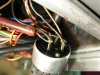
My unit currently has three wires coming from each motor to a large 2uF capacitor, but the colors of the wires don't match what is shown on the Revox document for the 60Hz conversion kit. The wires coming from my motors (which are the original 50Hz motors) are basically copper colored (clear jacket), but each one has a slight color tint to it. However, on the conversion doc, the wires are assigned specific colors, i.e., yellow, black, blue, violet, etc.). Does anyone recall whether the motor wires on their units have specific colors, or are they similar to the copper-tinted wires that I am seeing?

It appears to me that the 60Hz conversion wiring was somewhat botched by the previous owner. But since I don't have an original G36to look at, I have no idea how badly it was botched. If I can at least confirm which parts of the conversion appear to be correctly wired, it would make things much simpler. The attached file shows the 50Hz to 60Hz conversion info (top of page) and the wiring of my unit (bottom of page).
 

Attachments

  • motor-cap wiring - my unit.jpg
    motor-cap wiring - my unit.jpg
    72.4 KB · Views: 54
Last edited:
Register to hide this ad
The colour of the insulation fades with time. Try to push or peel back some of the yellow tubing, it will reveal the true colours. If you get the wires wrong, no harm will be done, the motor will just run backwards.
 
Wow, thanks for the quick response steerpike2! I will try peeling the jacket back. I also have to check whether the previous owner installed the 60Hz capstan or not (fingers crossed :-). Judging by the age & type of caps that were installed for the conversion, it seems possible that the factory 60Hz conversion kit was used.
Have a great day (or I guess it's now night in S. Africa?)
 
Well, no luck so far with the wire colors. I peeled the jacket back (way back :-) and the colors did become more distinct, but they still don't match the schematic. The wires from the motor seem to be colored yellow, green, copper. Guess I'll just have to wire them up and see if the motor turns in the right direction. That will have to wait however, as I still need to reform the caps first.
 
Hey captain! Haven't fogotten about you ... just been busier than I thought I would be.
After I opened up the G36, it appeared to be modified already for 60Hz power, although the mod doesn't seem to have been done correctly (at least for the motor/cap wiring). And I still need to check whether I have the 60Hz capstan that was part of the factory conversion kit or the original 50Hz capstan. Anyhow, reforming the caps is still my first goal, but I need to sort out the power issues first. Slow going :-(
 
Yellow & green are correct - the Revox manual I have shows those two, so maybe they ran out of violet & used clear / natural / copper instead.

I'll have a closer look on one I have in my store-room later tonight, see what it looks like to my eyes - but it will be 50Hz.
 
Much appreciated steerpike! Hope I can return the favor sometime :-) I forgot to mention earlier that my G36 is a MKII version (forgot the SN, but it's somewhere around SN 426XX), if that's of any importance.

BTW, on the 50Hz version, do you happen to know the pupose of the "tie point" (third terminal, pin J) on the 3.5uF motor caps (C72 or C71). Was it just there to provide a convenient place to join two wires? On the 60Hz conversion, the third terminal (pin 3) of the motor cap is actually used internally, so the original wires that were joined there have to be removed and joined externally.
 
I had a look at mine (not too well lit, i need to re-look in bright light) and there seems to be no violet wire - just an indistinct colourless insulated one, as well as the green-sh and yellow-ish ones.
As for the tie point, still need to figure out what is going on there... will get back on that.
 
I've sorta decided to go ahead and open up the beast and do a complete cleaning, oiling, and recap, so while I'm at it, I might as well create a wiring diagram too. Now that I've been studying the part placement and wiring, it doesn't seem quite as daunting. Actually was thinking it might be nice to connectorize some of the wiring that goes between the upper and lower chassis so that, in the future, I could just disconnect a wiring harness (instead of marking and then desoldering wires) to fully separate the two halves. Maybe a connector like they use on car stereo systems would work good, as they are also keyed to prevent plugging things in the wrong way.
I will post the wiring diagram and some pics once I get started (but it might take awhile, especially with the upcoming holidays).
 
Without looking at any schematics, or opening up one of my G36s, I'd take a wild guess that the tie-point that you mentioned might have something to do with wiring some winding in series for 240VAC, vs in pararllel for 120V. But again, this is nothing more than a guess.
 
Without looking at any schematics, or opening up one of my G36s, I'd take a wild guess that the tie-point that you mentioned might have something to do with wiring some winding in series for 240VAC, vs in pararllel for 120V. But again, this is nothing more than a guess.

Hmmm .. that could be. Part of the 60Hz wiring mod changes the motor connection to the 240V transformer tap. I'll keep that in mind when I start tracing the wiring.
 
Reel motor wiring (Revox G36 in particular)

Some of the more experienced R2R guys are probably already aware of the following, but I thought I'd post it for anyone else just starting out, as it wasn't immediately obvious to me.

After getting some pics of the motor cap wiring from a fellow AK'ers Revox G36 (graciously provided by Ibruun), I was at first dismayed because the color coded wires on my motor caps did not match his machine (or the original 60Hz conversion document that I had started with). However, after thinking about it for awhile, I realized that there are multiple ways that the wiring from the motor can be connected to the motor caps and still have it work correctly.

Essentially, when looking at the schematic, I visualized the motor symbol rotating clockwise (for left motor symbol) or counter-clockwise (for right motor symbol). If you assign a wire color to each corner of the motor symbol to start with, and then rotate the motor symbol, all this does is change the color of the wire used to interconnect to the rest of the circuit. As long as the wires from each corner of the motor symbol aren't criss-crossed, then the motor will turn in the proper direction.

In addition, when looking at the schematic, I was presuming that the top of the motor cap symbol was pin 1 and the bottom was pin 2, but obviously, this does not have to be the case. The top of the motor cap symbol could be pin 2 and bottom pin 1, which would simply change the color of the motor wire that is physically attached to each pin.

I was also presuming that the factory would have wired each machine the same way for consistency, but I remember seeing a comment from another AK'er that said some wiring may be different based on the technician that did the work. It would be nice to have a factory assembly/wiring diagram, but I haven't seen anyone claim to have a copy of one.

So, on the G36, it seems there are 6 possible color combinations of wiring that could be used to interconnect a motor with its motor cap. My plan now is to document those six combinations and then determine if my unit is aligned with any of them. If it is, then it should be OK.

For posterity, I'm attaching the Revox G36 motor cap pics supplied by Ibruun.
 

Attachments

  • Revox G36 - left reel motor pic1.jpg
    Revox G36 - left reel motor pic1.jpg
    76.5 KB · Views: 26
  • Revox G36 - left reel motor pic2.jpg
    Revox G36 - left reel motor pic2.jpg
    65.3 KB · Views: 19
  • Revox G36 - right reel motor pic1.jpg
    Revox G36 - right reel motor pic1.jpg
    50.7 KB · Views: 26
Last edited:
Back
Top Bottom