

You are using an out of date browser. It may not display this or other websites correctly.
You should upgrade or use an alternative browser.
You should upgrade or use an alternative browser.
RLJohns Sansui G-5700 Rebuild & Repair


Register to hide this ad

RLJohn
New Member
I received 2 Sansui G-5700 Receivers free from my friend and co-worker. 1 is a basket case with considerable damage to the exterior and a few pieces missing inside. The second one Powers up but has no sound output. The safely operate light does not light up. The FM Tuner seems to work great as far as I can tell. The protection relay does not click on. It appears as though someone has done some work on the R side of the F-2980 board and on the R Output. The picture above show these repairs. I'm hoping someone here can help me get this thing firing on all cylinders. Sorry guys I work at a car parts store so, I had to make a silly pun. Also if any users are from OKC area I would like some hands-on guidance if possible???
The second one Powers up but has no sound output. The safely operate light does not light up. The FM Tuner seems to work great as far as I can tell. The protection relay does not click on. It appears as though someone has done some work on the R side of the F-2980 board and on the R Output. The picture above show these repairs. I'm hoping someone here can help me get this thing firing on all cylinders. Sorry guys I work at a car parts store so, I had to make a silly pun. Also if any users are from OKC area I would like some hands-on guidance if possible???
ghazzer
Senior Member
Your pics did not come thru. I use a third party photo storage site and then just place the link in the post. That shows the entire photo in your post instead of having to switch back and forth. I have used PhotoBucket (no affiliation) but I would suggest a different service that is more responsive and has fewer hang-ups.
Copy the link of the photo into your clipboard, return to your post and click on the 'senic' icon to the right of the smiley face, then paste the link when prompted. You may need to click on the "OPTIONS" button below right, then the "PREVIEW" button to view the pic(S) before you save that post.
I will insert the X-Ray pics of my F-2980 pics for your use.


Copy the link of the photo into your clipboard, return to your post and click on the 'senic' icon to the right of the smiley face, then paste the link when prompted. You may need to click on the "OPTIONS" button below right, then the "PREVIEW" button to view the pic(S) before you save that post.
I will insert the X-Ray pics of my F-2980 pics for your use.
RLJohn
New Member
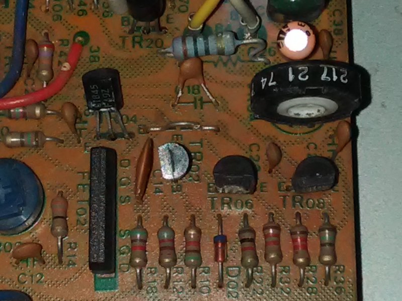
G-5700 Right side pot
This pot has been changed before. Should have been the same as the L side.
Last edited:


In the first photo is that the 21 turn pot. that everyone is suggesting?
Well, it has '21' painted on it, but that looks like a date code or batch number, probably not a descriptor of the part itself. If that is an original part, (it looks a bit weird), then it will very likely be a single turn trimmer resistor. BTW: What is everyone suggesting?
RLJohn
New Member
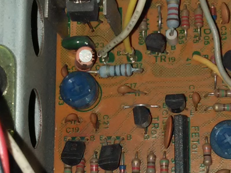
No its not original.Well, it has '21' painted on it, but that looks like a date code or batch number, probably not a descriptor of the part itself. If that is an original part, (it looks a bit weird), then it will very likely be a single turn trimmer resistor. BTW: What is everyone suggesting?
ghazzer
Senior Member
Yes, the small round blue ones are the original 100Ω, single turn trimmers. I don't recognize the large one with the "21" markings.
Does the "better" F-2980 show any indication of having been worked on before?
You can get a good deal on Bourne style trimmers here: http://www.taydaelectronics.com/potentiometer-variable-resistors/cermet-potentiometers/3296w.html . Also look for cheap prices on metal film 1% ¼ W resistors, terminal blocks and capacitors. You should probably get better quality components for anything that is directly in the signal path, but I find it hard to pass up ten resistors for 12¢. They do have a $5 minimum.
Does the "better" F-2980 show any indication of having been worked on before?
You can get a good deal on Bourne style trimmers here: http://www.taydaelectronics.com/potentiometer-variable-resistors/cermet-potentiometers/3296w.html . Also look for cheap prices on metal film 1% ¼ W resistors, terminal blocks and capacitors. You should probably get better quality components for anything that is directly in the signal path, but I find it hard to pass up ten resistors for 12¢. They do have a $5 minimum.
RLJohn
New Member
Yes, the small round blue ones are the original 100Ω, single turn trimmers. I don't recognize the large one with the "21" markings.
Does the "better" F-2980 show any indication of having been worked on before?
You can get a good deal on Bourne style trimmers here: http://www.taydaelectronics.com/potentiometer-variable-resistors/cermet-potentiometers/3296w.html . Also look for cheap prices on metal film 1% ¼ W resistors, terminal blocks and capacitors. You should probably get better quality components for anything that is directly in the signal path, but I find it hard to pass up ten resistors for 12¢. They do have a $5 minimum.
Yes the trimmer and the extra resistor on the audio output in the pictures are on the good board.

ghazzer
Senior Member
I have never (yet) had a problem with any of the parts I have ordered from them, but I have never ordered things I considered "critical". I have found it very convenient to stockpile a readily available supply of parts. Even when you have to buy at least ten, how can you go wrong at just over a penny each. This maybe anal, but with 20 or 30 a specific resistor in my stash it is easy to find one that will let me balance voltage levels between channels, at certain junctions.
Remember that it is NOT necessary to change a part that is still working correctly. The F-2980 bd is very finicky and has been known to oscillate when parts "get out of balance". This can even apply to the small "pumpkin" ceramic capacitors, especially when the tolerance is ±20% (or larger).
My advice is to get it running first, then go back and replace any questionable components.
Remember that it is NOT necessary to change a part that is still working correctly. The F-2980 bd is very finicky and has been known to oscillate when parts "get out of balance". This can even apply to the small "pumpkin" ceramic capacitors, especially when the tolerance is ±20% (or larger).
My advice is to get it running first, then go back and replace any questionable components.
Last edited:
ghazzer
Senior Member
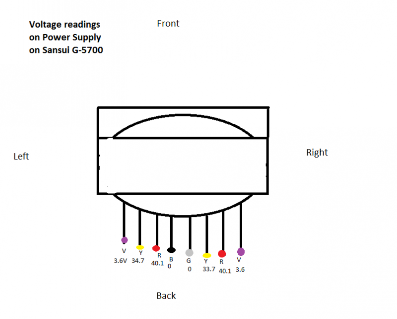
OK. What do you think of your voltage readings? Did you measure the line voltage for a reference?
First, I recommend that you use mini-grabbers with your DMM. Connect the grabbers with power off, give everything a visual check, then apply power to get your readings. These readings will be a little lower than expected if you are using a DBT.
There are several places in the P/S where voltages are marked on the schematic. I would check those next.
Note that there are two circled numbers (5 & 6) coming off the filter caps, just above and to the left of the F-2868, Speaker Selector. These are the rail voltages: 5 = +54vdc & 6 = -54vdc. From the filter caps they are routed to every place where you see the circled 5 or 6.
Voltage levels wrt ground are marked at several places in the right channel and should be the same in the left chanel.
Ii things are OK so far I'd replace the 100Ω trimmers before proceeding any further with power applied.
First, I recommend that you use mini-grabbers with your DMM. Connect the grabbers with power off, give everything a visual check, then apply power to get your readings. These readings will be a little lower than expected if you are using a DBT.
There are several places in the P/S where voltages are marked on the schematic. I would check those next.
Note that there are two circled numbers (5 & 6) coming off the filter caps, just above and to the left of the F-2868, Speaker Selector. These are the rail voltages: 5 = +54vdc & 6 = -54vdc. From the filter caps they are routed to every place where you see the circled 5 or 6.
Voltage levels wrt ground are marked at several places in the right channel and should be the same in the left chanel.
Ii things are OK so far I'd replace the 100Ω trimmers before proceeding any further with power applied.
Ok started testing diodes on my f-2980 board. zd601 right by the protection relay reads from both directions. Is this possibly the problem?
You need to lift one end of a diode in this position - as you are measuring through the relay coil and not the diode.


