

You are using an out of date browser. It may not display this or other websites correctly.
You should upgrade or use an alternative browser.
You should upgrade or use an alternative browser.
ROTEL ROTEL - Ground Hum From Milan to Minsk
- Thread starter JB8
- Start date

Voltages shown in service manuals are sometimes a bit off. Check that any voltage selector is set to match mains AC voltageIs the +42V DC at B1 something to worry about or is that fine and close enough to 36V
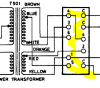
Connect probe GND to chassis, eg, phono GND. Set coupling to AC, approx 200-500mV/div and 1-10mS/div on time base. Looking for a 60Hz waveform. There certainly will be a 120Hz rectified ripple, maybe 200-500mV, this is normal/expected.In your last post you mentioned checking the ripple, can you tell me how my scope should be set up to test ripple?
Yes and no, you could convert to a star based GND scheme though I would need to check current implementation. Also in this case you have mains 60Hz hum and the star GND is more for 120Hz. I'd be using the scope as a first step.Is there a grounding hack I can try where I change or augment the grounding points?
I think that it's unlikely that the rectifier has failed but it needs to be checked.If we have excess ripple at that point, what mitigating steps do we have to kill it considering the AC really shouldn't be getting to this point?
From left field, have you replaced the lamps with LEDs? What value resistor did you use?
Will check the pix for wiring layout...
Easiest to test for ripple at main cap, red wire
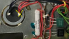
expect 120Hz rectified waveform. 60Hz wave would point to failed rectifier, amp would not work if failed so best to look elsewhere.
May seem a bit flakely but I'd use something non-conductive like a chopstick and put pressure on each wire from underneath and note any change .
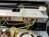
Also check screws highlighted yellow. Red highlights are not ideal. Check green highlight, expect black wire connects to GND point below 1000uf/35V caps. If not already done, reflow solder connections marked in red.
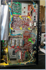
expect 120Hz rectified waveform. 60Hz wave would point to failed rectifier, amp would not work if failed so best to look elsewhere.
May seem a bit flakely but I'd use something non-conductive like a chopstick and put pressure on each wire from underneath and note any change .
Also check screws highlighted yellow. Red highlights are not ideal. Check green highlight, expect black wire connects to GND point below 1000uf/35V caps. If not already done, reflow solder connections marked in red.

JB8; I know it's miniscule, BUT! You have 2 voltages listed at B1. One is in a rectangle. The other is open. Look for a voltage legend on the schematic lists parameters to be met with a voltage in a rectangle. Sometimes that particular voltage will be dependent on a specific setting on the function switch (ie: Open FM MPX, rectangle FM MONO or some such.
3 quick examples
Sansui 2000
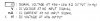
Pioneer SX-780
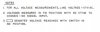
'69 Fisher 250-TX
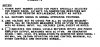
Note that each one is different. You'll probably get slightly higher voltages with the selector in any other position than what your's specifies. But not 20% higher. Shouldn't be any more than 10% variation from spec, provided your input line voltage is 117-120VAC.
3 quick examples
Sansui 2000
Pioneer SX-780
'69 Fisher 250-TX
Note that each one is different. You'll probably get slightly higher voltages with the selector in any other position than what your's specifies. But not 20% higher. Shouldn't be any more than 10% variation from spec, provided your input line voltage is 117-120VAC.
An audiophiles strange electric journey.......... haha, Seinfeld is the bestJust a tip of the hat for the Seinfeld reference. Nothing of value to add, I'm afraid.

JB8
Well-Known Member
Gentlemen, thank you for these great replies, lots to consider here and I'll be digging in shortly.
Turns out I finally got COVID, and wow, it was a doozy. Had a dream during the fever stage in which I was desperately combing the internet for a schematic of JB8, really felt like I had a bad cap or transistor someplace in my circuit but had no luck finding the bad component. This hobby has officially taken my brain, ha!
@mbz and @larryderouin , I'm eager to get after this and sincerely appreciate your time and effort here. Update coming soon!
Turns out I finally got COVID, and wow, it was a doozy. Had a dream during the fever stage in which I was desperately combing the internet for a schematic of JB8, really felt like I had a bad cap or transistor someplace in my circuit but had no luck finding the bad component. This hobby has officially taken my brain, ha!
@mbz and @larryderouin , I'm eager to get after this and sincerely appreciate your time and effort here. Update coming soon!
JB8
Well-Known Member
From left field, have you replaced the lamps with LEDs? What value resistor did you use?
Even though I'm still a few stubbies short of a six-pack I had to at least address this tonight, I'll pull the scope and go deeper ASAP but this is some low hanging fruit.
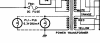
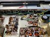
I have yet to add any resistors to this lighting system, so I'm eager to know what you'd advise considering this configuration. I've added reference pics as well specific to voltage specs and layout. Even if this doesn't cure the issue I'm excited to confirm either way.
Currently Installed:
- Dial Pointer - was out, replaced with 8V 70mA incandescent
- Stereo Beacon - original lamp still working
- Dial & Meter - replaced with 6 Green 8V 20mA fuse LED's


Sounds like you've been at the sheep dip again...Even though I'm still a few stubbies short of a six-pack
On the lamps, trying to rule out a bad implementation as a possible cause for hum, yeah it's left field.
Most vintage amps used incandescent bulbs, these generally have a higher voltage drop than LED's.
The idea behind the resistors is mostly to get the volt drop of the LED+resistor to equal the volt
drop of the bulb.
Looking at the dial and meter lamps, PL1...PL6 6.3Vac 280mA. First thing to note is that it's an AC supply
and LEDs "work best" on DC. The LED's will act as a rectifier so they will see a +ve voltage and also a -ve/reverse
voltage. So the LED's will be pulsed on 50/60 times per second (Hz), they will also see a reverse voltage at 50/60Hz.
Moreso the reverse voltage, this causes a shortened life.
Typical options are,
1) replace bulb with LED and resistor and accept shortened life (replace every few years?)
2) replace bulb with diode (1N400x) to perform rectification and take brunt of Vreverse then add resistor and LED
3) as 2) but add a smoothing cap, say 10-47uf. I consider this option unnecessary/overkill consider for bright
LEDs where you see a flicker.
Looking at 2)...
The 1N400x will convert the 6.3Vac into half wave rectified, using the 6.3V peak voltage as worst case. The LED will
have a forward volt drop and current draw, see datasheet, typically something like Vf=2.2V and 20-50mA, using 20mA
in your case...
Allow 0.7V for 1N4001 and 2.2V for LED means we need to burn 6.3-0.7-2.2=3.4V in the resistor with 20mA current
ie. 3.4/0.02 = 170ohms, round up to next common size 180ohms. Or 205ohms for option 1), so round up to 220ohms...
Looking at what you have done, the 8V LEDs is higher than the 6.3Vpeak so no further volt drop is required. At most I'd add a 1N400x from the supply to handle the reverse voltage/current.Dial & Meter - replaced with 6 Green 8V 20mA fuse LED's
JB8
Well-Known Member
Finally busted out the scope, saw the rectified 120 Hz cycle wave at the main filter cap as you predicted, did not find any other points that showed a 60 Hz wave. I also checked all the points from post #43, no luck in probing with chopstick, reflowing ground points, etc. Installed diode to handle reverse voltage/current, also no change.
If this is indeed a power supply issue and likely can't be tied to any other boards or components I suppose this is now just a cute, noisy, paper weight. I definitely put too much time into this thing and don't want to waste any more of anyones valuable input and brain power on this guy, so if no one is keen on trying to crack the case I may just need to cut my losses and move on. It's a shame but I know this scenario can be one of the most elusive buggers to solve.
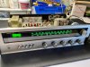
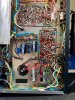
If this is indeed a power supply issue and likely can't be tied to any other boards or components I suppose this is now just a cute, noisy, paper weight. I definitely put too much time into this thing and don't want to waste any more of anyones valuable input and brain power on this guy, so if no one is keen on trying to crack the case I may just need to cut my losses and move on. It's a shame but I know this scenario can be one of the most elusive buggers to solve.
Yeah, the hum at main caps/failed rectifier was a long shot that needed to be ruled out, expect that the amp would not work so well with failing rectifier. I assume that all peaks of the waveform had equal size rather than every second peak being higher??? Hum that doesn't increase with volume indicates hum introduced after volume control which means the power amp stage is of interest. You could try probing at various stages of the audio path. Certainly check at speaker connectors, verify 60Hz, then probe the wiper (middle pin) of the volume pot or at C601, expect no 60Hz. Also check at base of driver transistor (or connected part), eg, TR604,5b (R608, VR602 wiper)Finally busted out the scope, saw the rectified 120 Hz cycle wave at the main filter cap as you predicted, did not find any other points that showed a 60 Hz wave.
JB8
Well-Known Member
The peaks of the waveform were pretty equal. I am seeing what looks like a 60 Hz wave at the speaker connectors, but not with the speaker switch engaged? I may be botching the test but I can see a rolling wave but then with the speaker switch engaged it goes flat. Def a significant pop as well when engaging the speaker switch, which I know is typical, but it's louder than I would expect considering all the PS caps that have been replaced.
No 60Hz at C601 or at R608.
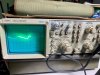
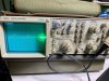
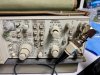
Pic one is what I'm assuming is the 120 Hz rectified wave at the positive terminal of the main filter cap, pic #2 is positive speaker terminal post without speaker switch engaged. I'm still getting used to using a scope so my findings could be suspect.
No 60Hz at C601 or at R608.
Pic one is what I'm assuming is the 120 Hz rectified wave at the positive terminal of the main filter cap, pic #2 is positive speaker terminal post without speaker switch engaged. I'm still getting used to using a scope so my findings could be suspect.
Good info above.
Pic #1 looks like 3.1 divisions at 2mS/div approx 150Hz. Maybe some
probe compensation needed. There is normally a test pin on the front panel
that gives a 1kHz square wave signal. If present connect your probe to it
and adjust the very outer knob on the time base to give 1kHz. Likewise adjust
the outer knob on the Volts/Div to give a square wave. Maybe try the "probe
attentuation" port.
Pic #2 looks like 2.6 divisions at 5mS/Div, about 75Hz, so yeah mains frequency.
Pic #1 looks like 3.1 divisions at 2mS/div approx 150Hz. Maybe some
probe compensation needed. There is normally a test pin on the front panel
that gives a 1kHz square wave signal. If present connect your probe to it
and adjust the very outer knob on the time base to give 1kHz. Likewise adjust
the outer knob on the Volts/Div to give a square wave. Maybe try the "probe
attentuation" port.
Pic #2 looks like 2.6 divisions at 5mS/Div, about 75Hz, so yeah mains frequency.
EDIT: Strange question, did you have speakers/wires connected when you took this measurement? That would provide some sort of path from chassis/black terminal via speaker/crossover to the red terminal???I am seeing what looks like a 60 Hz wave at the speaker connectors, but not with the speaker switch engaged?
Yeah, a pop is typical on cap coupled amps, though maybe there is some issue there with 60Hz on the spkr connectors when speaker selector is off. Need to sleep on that, maybe check solder connections/wiring from speaker selector to speaker connectors also check proximity of any AC power wires to these speaker wires, try the chopstick in this area.Def a significant pop as well when engaging the speaker switch, which I know is typical,
Last edited:
JB8
Well-Known Member
I used the probe calibration and was able to achieve that 1K square wave you noted, then remeasured at the main filter cap and got a similar result.

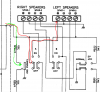
I also jumpered a speaker in at the headphone feeds (yellow arrow's), no hum, very low output levels, then jumped in at the green arrow's and got that nice loud hum I'm used to.
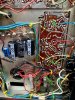
I checked the speaker connectors, all seems as it should, additional probing with chopstick as well revealed no significant changes in hum level.
Curious if a bad Zener at D902 could impact the issue? I removed it and tested it but wanted to confirm whether I should circle back to make sure it's functioning as it should. I don't have a 12V Zener on hand but would appreciate your opinion.
Also, I'm not getting that 60 Hz at the speaker terminal anymore, not sure if I had the speaker connected when I did that bit of testing but I know the probe was certainly grounded.
I also jumpered a speaker in at the headphone feeds (yellow arrow's), no hum, very low output levels, then jumped in at the green arrow's and got that nice loud hum I'm used to.
I checked the speaker connectors, all seems as it should, additional probing with chopstick as well revealed no significant changes in hum level.
Curious if a bad Zener at D902 could impact the issue? I removed it and tested it but wanted to confirm whether I should circle back to make sure it's functioning as it should. I don't have a 12V Zener on hand but would appreciate your opinion.
Also, I'm not getting that 60 Hz at the speaker terminal anymore, not sure if I had the speaker connected when I did that bit of testing but I know the probe was certainly grounded.
The headphone feed (green) is the same as the speaker feed (red), possibly the headphone resistors R920,1 are attenuating the signal/hum so you don't notice it. Try setting the Volts/Div to 0.1 or lower.I also jumpered a speaker in at the headphone feeds (yellow arrow's), no hum, very low output levels, then jumped in at the green arrow's and got that nice loud hum I'm used to.
Do you have headphone? They tend to be more sensitive so hum should be more noticeable...
Also try setting the 4CH speaker selector to 4 Channel, don't connect additional speakers.
D902 (12V) is for the tuner stage, it may be sagging but it's essentially connected to the main filter cap where waveform looked ok. I'd look elsewhere.Curious if a bad Zener at D902 could impact the issue? I removed it and tested it but wanted to confirm whether I should circle back to make sure it's functioning as it should. I don't have a 12V Zener on hand but would appreciate your opinion.
Can you reconnect speakers, set speaker selector to off and then check waveform at red speaker connector, connect probe GND to chassis/phono connector. Then probe any (eg AUX) RCA GND/outer connector
JB8
Well-Known Member
Do you have headphone? They tend to be more sensitive so hum should be more noticeable...
Checking with headphones regularly, definitely attenuated but the hum is still there and noticeable.
Can you reconnect speakers, set speaker selector to off and then check waveform at red speaker connector, connect probe GND to chassis/phono connector. Then probe any (eg AUX) RCA GND/outer connector
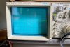
With speakers connected, speaker selector(s) off, in 4 channel position, if I really crank the Volt/Div I get this weird rolling wave. Did not see any wave when at .1, needed to go down to 20mV and pull the 5X mag button out to see this signal.
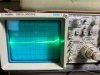
Probing the RCA GND/outer connectors I didn't detect anything. (probe GND connected to phono ground/chassis)
That's better, more consistentChecking with headphones regularly, definitely attenuated but the hum is still there and noticeable.
Not sure about this. On one hand thinking the hum is "in" the GND circuit and you are seeing the difference (oscilloscope GND connection v probe) between the hum in the GND plane and audio path. However no hum at the volume wiper shoots this theory down. Maybe redo volume wiper but try at 20mV/Div...With speakers connected, speaker selector(s) off, in 4 channel position, if I really crank the Volt/Div I get this weird rolling wave. Did not see any wave when at .1, needed to go down to 20mV and pull the 5X mag button out to see this signal.
I need to look at the power amp board physical layout/connections, especially the GND connections. You could try measuring the resistance between various GND points and phono GND, especially on the power amp board. A difference of a few tenths on ohms is enough to cause issues.
JB8
Well-Known Member
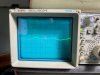
No 60Hz at C601 or at R608 but this is what the waveform looked like at 20mV/Div when probing R608 specifically.
It's kind of a rolling, spastic wave, not sure if it reveals anything but I'm certainly happy to keep checking any and all points.
I measured resistance between ground points and phon0 ground from a multitude of spots, most of which would start out at a two to a few tenths of ohms then would retreat back to 000.0 ohms. I've been tightening screws here and there - backing them off a bit then snugging them up - no change.
I even hooked up an old Realistic outboard phono amp to via the AUX ports to essentially add another grounded source and it didn't change things. Not terribly surprised but again, happy to exhaust all of our options.
It's kind of a rolling, spastic wave, not sure if it reveals anything but I'm certainly happy to keep checking any and all points.
I measured resistance between ground points and phon0 ground from a multitude of spots, most of which would start out at a two to a few tenths of ohms then would retreat back to 000.0 ohms. I've been tightening screws here and there - backing them off a bit then snugging them up - no change.
I even hooked up an old Realistic outboard phono amp to via the AUX ports to essentially add another grounded source and it didn't change things. Not terribly surprised but again, happy to exhaust all of our options.
Yeah, not sure what that waveform is. I'd be guided by the waveform you see
at the speaker connectors, this is what you hear, need spkr selector set to ON.
Don't see any pix of the 60Hz at the speaker connectors, post a pic...
C601 is the volume wiper, confirms earlier measurement, problem in power amp, speaker selector...
but both channels affected, not convinced it's a power amp issue...
No AC/hum on R608 is puzzling, this is unregulated supply, should be 120Hz ripple same as
main filter caps (AC coupling on?)
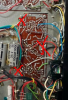
Measure the resistance between the black wire (red cross) and either green wire then repeat for black and other green wire. The green wires are the GND from the preamp while the black wire connects to the black on the main filter cap.
Measure your MM probe/leed resistance by shorting probes together, expect 0.4-0.6ohms, anymore than about
0.2 ohms above this figure should be investigated.
at the speaker connectors, this is what you hear, need spkr selector set to ON.
Don't see any pix of the 60Hz at the speaker connectors, post a pic...
C601 is the volume wiper, confirms earlier measurement, problem in power amp, speaker selector...
but both channels affected, not convinced it's a power amp issue...
No AC/hum on R608 is puzzling, this is unregulated supply, should be 120Hz ripple same as
main filter caps (AC coupling on?)
Measure the resistance between the black wire (red cross) and either green wire then repeat for black and other green wire. The green wires are the GND from the preamp while the black wire connects to the black on the main filter cap.
Measure your MM probe/leed resistance by shorting probes together, expect 0.4-0.6ohms, anymore than about
0.2 ohms above this figure should be investigated.
JB8
Well-Known Member
Don't see any pix of the 60Hz at the speaker connectors, post a pic...
This is what the wave looks like for both channels, positive speaker terminal to probe, probe ground connected to phono ground, 20 mV V/Div, speaker switch set to ON.
No AC/hum on R608 is puzzling, this is unregulated supply, should be 120Hz ripple same as
main filter caps (AC coupling on?)
Checked R608 and counter part (yellow arrows) and C601 (circled) again, not seeing any waves, yes, AC Coupling is on the scope as well. I'm assuming I've got the correct resistors, checked them with the DMM and found ~3.5K ohms.

Measure the resistance between the black wire (red cross) and either green wire then repeat for black and other green wire. The green wires are the GND from the preamp while the black wire connects to the black on the main filter cap.
I'm getting roughly .2 ohms when testing resistance between the green and black wires, both segments had the same measurement. My DMM, a UNI-T89X, indicates it should have between .1-.3 ohms with the leads shorted, mine is right there at .2 ohms when shorting the leads. Assuming we should essentially see zero resistance between these specific ground points?
All good above...
Looks like your oscilloscope has problems with the time base circuit, for 60Hz expect about 15mS between peaks. The 120Hz rectified wave at filter cap was also out. But that is not the point, waveform clearly present at speakers, no waveform at volume wiper points to problem in power amp stage. Try probing various points in power amp, start at output transistors, ie, TR606,7 base.
Running out of ideas...
Looks like your oscilloscope has problems with the time base circuit, for 60Hz expect about 15mS between peaks. The 120Hz rectified wave at filter cap was also out. But that is not the point, waveform clearly present at speakers, no waveform at volume wiper points to problem in power amp stage. Try probing various points in power amp, start at output transistors, ie, TR606,7 base.
Running out of ideas...