

You are using an out of date browser. It may not display this or other websites correctly.
You should upgrade or use an alternative browser.
You should upgrade or use an alternative browser.
running a XO rebuild parts list by ya...
- Thread starter cdfac
- Start date


Hey Ken, if you were asking a question about the resistors, stick with the non-inductive ceramics like you already have. There was no up-side to the old series-parallel nightmare in our earlier x-overs.
Concentrate on the caps, and re-arrange the inductors as Chris did to avoid stray fields.
Concentrate on the caps, and re-arrange the inductors as Chris did to avoid stray fields.

Ok I am back with these filling my cart as I want to get all my projects wrap up in the next few weeks, as far as speaker rebuilds. I have these QLS-1's that I am recapping and replacing all the mid domes with new NOS ones. But I have noticed a difference on mine from both the spec sheet and Chris's. My EMIT's the spec schematic shows three caps, a 2.5, 1.75, and a 1.25. Yet mine has three 2.5's and one 1.25. Should I copy what I have or follow the specs, any one have an opinion? And rather than rearranging the inductors can't you install a shielding of some sort.
If you look at the picture I posted when I first started on the left right above those pots you can see clearly there are four caps, these are all wired into the selector for the crossover of the EMIT's three of them are the same, 2.5's and then one 1.25. By the looks of the way they wired them, the two 2.5uf's are wired in a series, then the one 2.5 and then the 1.25. I am thinking just follow the specs rather than copy this.
If you look at the picture I posted when I first started on the left right above those pots you can see clearly there are four caps, these are all wired into the selector for the crossover of the EMIT's three of them are the same, 2.5's and then one 1.25. By the looks of the way they wired them, the two 2.5uf's are wired in a series, then the one 2.5 and then the 1.25. I am thinking just follow the specs rather than copy this.
Last edited:
i would stick with the three different values in the spec sheet. i think i have seen something like that before, but the way the spec sheet has it makes the most sense. you'll probably end up sticking with the middle crossover point anyway.
I have mainly used the middle crossover when using them. Chris if I recall, you used a bunch of caps in parallel for your Waktins to come up with the final value, I am wondering and I also asked this over at the manufactors thread, can you not use a cap like the one linked below or is it not audio grade and not work well? It sure would be a lot easier and neater.
http://www.mouser.com/ProductDetail...=sGAEpiMZZMtZ1n0r9vR22U3BqEK3KIgOEyiy5l1a0ZQ=
I have mainly used the middle crossover when using them. Chris if I recall, you used a bunch of caps in parallel for your Waktins to come up with the final value, I am wondering and I also asked this over at the manufactors thread, can you not use a cap like the one linked below or is it not audio grade and not work well? It sure would be a lot easier and neater.
http://www.mouser.com/ProductDetail...=sGAEpiMZZMtZ1n0r9vR22U3BqEK3KIgOEyiy5l1a0ZQ=
Those Spragues are NOT non-polar caps like the originals and won't work in speakers. You'll need a bunch of NPE's in parallel like Chris used, or measure your existing caps to see if they're still in spec.
KraftwrkTrbo
Active Member
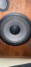
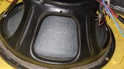
Quantum 2 rebuild here: measure the woofer coils. Both speakers measure 14mH, yet every diagram shows 20 mH. They don't 'age' as far as I know. And both show same value. Has anyone else measured the L? Or heard about deviation from drawing values to actual values?
KraftwrkTrbo
Active Member
KraftwrkTrbo
Active Member
What is the mathematical difference between 14 mH and 20 mH in that path in conjunction with the 1400 microF cap?