
• The move to the new server is done. There are some software and database maintenance updates in process. This has us passing the hat around to help out. We appreciate any donations. Seriously, even a dollar helps. The payment page may be found here - https://www.audiokarma.org/support.html

SA-6500II Rebuild high dc offset.

QSilver

Super Member
Picked up one of these with a few problems. Had some bad crackle on one channel which i think i have tracked down to the outputs. I pulled out the outputs and the crackling has gone from my scope.

On the left channel, i had a dc offset of 80mv and 20mv on the right. I started working the left channel first and replaced the differential pair with a pair of gain matched KSA992's which dropped the offset to 60mv.

I then swapped out the rest of the transistors for the left channel leaving the outputs disconnected. Despite changing the transistors, checking resistor values, and replacing the eletrolytics and the single tantalum cap, the offset won't drop below 60mv! Im a bit stuck for ideas forth problem now. I've even gain matched the KSA1031 and the KCS2383 in the driver stage with no difference...

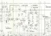
I've taken measurements on the bases of Q7 and Q9 which, according to the schematic, should read 0V. Here, they read 88mV each. Compared to 40mV and 32mV on Q8 and Q10.

I think this means that something here is not quite right.... I've even tried removing the decoupling cap C47 to isolate it from the tone circuitry but that didn't help... what am I missing here?

I've replaced the transistors using cross references I found in another 6500II thread here:

http://www.audiokarma.org/forums/index.php?threads/re-do-an-sa-6500ii.614242/page-2
 

Attachments
  • SA-6500II SM.pdf
    SA-6500II SM.pdf
    208 KB · Views: 6
  • SA-6500II amp section.jpg
    SA-6500II amp section.jpg
    84.8 KB · Views: 9
Last edited:
Register to hide this ad
I think the issues are that the circuit itself isn't balanced, and the higher the HFE of the input transistors, the less the problem. The voltages (88,40, and 32 mV not 0 volts) are due to the base currents. So the higher the current gain, the lower the base current. Also, the input side runs at about 0.5 mA while the other runs at about 1 mA., so lower base current, but less voltage drop because the resistor they current goes through is smaller (10k vs. 82k) So high HFE should produce less offset, And having a higher HFE transistor on the input side will reduce offset further, Decreasing R57 1.3k to 1k or increasing R55 20k to 30k will balance the currents, but make off set worse because of the difference in base resistors. My choice would be to select the input transistor for highest HFE and let it go if it looks good. I'm sure there are more complicated ways of adjusting off set, but would require more parts and could introduce other issues. IMO I don't think there is anything to worry about. Good luck
 
Last edited:
Hey I picked up this exact amp last weekend at an estate sale. I will be following this thread. The one I got seems to work just fine, but I might replace some of the caps. I think it's a real beauty of an amp with that silver face.
 
I think the issues are that the circuit itself isn't balanced, and the higher the HFE of the input transistors, the less the problem. The voltages (88,40, and 32 mV not 0 volts) are due to the baase currents. So the higher the current gain, the lower the base current. Also, the input side runs at about 0.5 mA while the other runs at about 1 mA., so lower base current, but less voltage drop because the resistor they current goes through is smaller (10k vs. 82k) So high HFE should produce less offset, And having a higher HFE transistor on the input side will reduce offset further, Decreasing R37 1.3k to 1k or increasing R37 20k to 30k will balance the currents, but make off set worse because of the difference in base resistors. My choice would be to select the input transistor for highest HFE and let it go if it looks good. I'm sure there are more complicated ways of adjusting off set, but would require more parts and could introduce other issues. IMO I don't think there is anything to worry about. Good luck

Thanks for the description. I think I understand... so are you suggesting that I need to alter the gain matching on the differential pair? I did try to measure the HFE on the original transistors but couldn't get a reading.... I might try and get a reading from them again... I could try swapping the differential pair from the other channel to this one as that one is giving me 20mV as opposed to 60mV.

What I don't understand is, no matter what I change there is no difference in the offset. I have changed many of the resistors... some had a baked look to them. Would putting the output transistors back into circuit help lower it? Though I think that the answer to that might be no...

Hey I picked up this exact amp last weekend at an estate sale. I will be following this thread. The one I got seems to work just fine, but I might replace some of the caps. I think it's a real beauty of an amp with that silver face.

Its a great looking amplifier, the one I got doesn't look to have a single scratch on it! I've taken the facia off while I work on it and given it a good scrub with cheap toothpaste and a soft brush and then a polish and it looks great. Can't wait to put it all back together. I might change the pilot lamp out for an LED as it looks quite easy on this model but we'll see.... :idea:
 
Yes put the o/p bjt back in, then measure again. I agree about the hfe of the transistors, 2sa640 have gains to 1000 vs a992 do not get that high.
Like sregor said the diff amp is not balanced, does not have any emitter degeneration resistors either, so its front end design is not optimal.
This is why it is hard to get a lower DC offset.
The design does not even have a way for adjusting o/p stage idle current, all in an effort to save a few $'s. there is the crude R63 strap option however.
Now do you really want lower offset?, then you will have to do mods. But i do not think it is worth the effort.
You can even put back the original a640 and see what they do, assuming that they were not the source of your cracking problem to begin with.
Decreasing R37 1.3k to 1k or increasing R37 20k to 30k will balance the currents, but make off set worse because of the difference in base resistors.
I think he meant to say R57!!
 
Well I thought I would compair the differential pair with the one I had pulled. I was beginning to think their gain was higher than the ones I put in so I was on the right track... Q8 and Q10 HFE were 480 and 520 respectively so I then went back and emasured the HFE of the 640's out of the left channel. They did have lower HFE, 420 and 480 but I put them back in circuit, matching the position of the higher gain transistor in the right channel and... Now I've got 15mV. So I've left that as is for now.

While I was here, I tested the outputs for their HFE. both the PNP's tested at around 120 but the NPNs were about 38 and 40 so it's looking like they're getting a bit tired... I'm ordering some TIP41C's and TIP42C's to replace them with. In the mean time, I have recapped the amplifier and replaced some baked resistors and cleaned up the facia. As soon as the new transistors arrive, I'll put them in and report back.

I would be curious about finding a high gain replacement for the 640's...
 
I finished rebuilding the amp today and fitted the new outputs - some TIP41C and TIP42C's. All seems to be well except for the fact I have idle current upwards of 80mV on DBT with the output transistors getting warm. Do I need to adjust the biasing for these different transistors? I don't need to gain match the outputs do I? As I think the NPN and PNPs are adversely different with the batch I got.... :(
 
Last edited:
Any ideas? I measured the hfe of another pair from the same ones I bought and the NPN is around 450 and the PNP is around 220. Is this maybe the reason? I'm not sure as there seems to be two schools of thought for gain matching outputs...
 
Back
Top Bottom