Hi all,
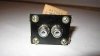
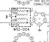
I'm new to AudioKarma and restoring vintage amps. I have a Pioneer SA-7100 that I have spent some time trying to figure out what is wrong. The left channel is much lower than the right channel. I think I have traced it back to the AWW-004 part. Oddly, this part on the schematics, it says AWW-044, but on the actual part, it is AWW-004. I can't find anything on this part other than in the service manual that says "Compound part for REC terminal" (see below). Another thing is that there are two service manuals, one has more information for troubleshooting and the other has the schematic and foil traces.
This is the one that matches mine:
https://www.vintageshifi.com/repertoire-pdf/pdf/telecharge.php?pdf=Pioneer-SA-7100-Schematic.pdf
This is the other service manual:
https://www.audioservicemanuals.com...a-7100/2468986-pioneer-sa-7100-service-manual (screen shots below). The manual above doesn't have part #s, etc.


It is an odd part. It looks like a capacitor but has 4 inputs. Does anyone know where I would find this part or what I would be able to do to fix this?
Thanks!
I'm new to AudioKarma and restoring vintage amps. I have a Pioneer SA-7100 that I have spent some time trying to figure out what is wrong. The left channel is much lower than the right channel. I think I have traced it back to the AWW-004 part. Oddly, this part on the schematics, it says AWW-044, but on the actual part, it is AWW-004. I can't find anything on this part other than in the service manual that says "Compound part for REC terminal" (see below). Another thing is that there are two service manuals, one has more information for troubleshooting and the other has the schematic and foil traces.
This is the one that matches mine:
https://www.vintageshifi.com/repertoire-pdf/pdf/telecharge.php?pdf=Pioneer-SA-7100-Schematic.pdf
This is the other service manual:
https://www.audioservicemanuals.com...a-7100/2468986-pioneer-sa-7100-service-manual (screen shots below). The manual above doesn't have part #s, etc.
It is an odd part. It looks like a capacitor but has 4 inputs. Does anyone know where I would find this part or what I would be able to do to fix this?
Thanks!