• The move to the new server is done. There are some software and database maintenance updates in process. This has us passing the hat around to help out. We appreciate any donations. Seriously, even a dollar helps. The payment page may be found here - https://www.audiokarma.org/support.html

SA-7500II has very low voltage readings on the outputs

Rob357

New Member
I picked up a broken Pioneer SA-7500II for $75. Knowing it has issues, all the fuses were removed. So I decided to save it, came home and replaced the fuses and put it on the dim bulb tester. It lit up like a Christmas tree. After unsoldering the outputs I tested them on the DCA75, one channel had shorted leads. It has smoked the 150 ohm and .5 ohm resisters. I replaced them all with the njw0302G and the njw0281G. It passed the test and sounded OK. So I went ahead with a recap and small transistor overhaul. It does have a channel with over 70mv so I checked the voltage at the outputs. Collectors about + and - 38.5 volts. The I read the bases, way low at + and - .6 volts. The emitters are way low at .05 volts. I have poured over the schematic looking for my missing 1.2 volts thinking without that I cannot get good voltage at the emitters. I have 1.2v at the base of Q11 and Q12. -1.17v at Q9 and Q10. Where did my 1.2 volts go? Or is the emitter voltage my issue? Or both? I am at the limit of my knowledge in circuits. I could have been advised wrong on replacement transistors as well. I will take readings wherever I need to and will pull and check whatever parts necessary. I have been frustrated by this unit but I know this is the learning experience I need. One bright note is that the outputs fit pretty well in the heatsink. I used a 3mmx10mm long button head screw to secure them and turned the mica 90 degrees. A set of long medical forceps was used to hold the tiny nuts for tightening. Also found a drop in replacement for the main filter caps, more on that later. Thank you,
Rob
 
Register to hide this ad
You may not have a problem, your post is a little unclear.
Expected voltages are (about)
Q11b +1.2V
Q11e/B15b +0.6V
Q15e +xxmV
Q13e -xxmV
Q13b/Q9e -0.6V
Q9b -1.2V
I have 1.2v at the base of Q11 and Q12
looks ok
-1.17v at Q9 and Q10
also looks ok
ollectors about + and - 38.5 volts. The I read the bases, way low at + and - .6 volts.
Q13, 15? +/-0.6 is expected, so ok.
 
Thank you for responding. I was looking at pre drivers because the final output readings are low. Q13 and Q14 base at -.6v, emitters at -.05v. Q15 and Q16 base at +.6v and emitters at +.06. The schematic shows the bases should be + or - 1.2v and the emitters at + or - .6v. Am I missing something?
 
Check this post, it may answer your questions
 
 
The schematic shows the bases should be + or - 1.2v and the emitters at + or - .6v. Am I missing something?
I must be looking at the wrong schematic. Emitters of Q13,14,15,16 are not +/-0.6V, expect xxmV.
Provide screen shot of the schematic.

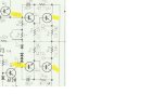
This is what I'm looking at,
 

Attachments

  • 7500ii.jpg
    7500ii.jpg
    38.4 KB · Views: 6
OK, your attachment is the board layout/artwork not a circuit schematic.
The voltages given in the board layout are indeed wrong and do not agree with the voltages given in the schematic.

Approximate voltages are given in post #2, appears that you do not have a problem in this area.
If you disagree with the post #2 voltages then I suggest you do the "math" starting between the emitter resistors (R57, R59), ideally DC offset at 0mV then allow 0.6V for each b-e junction.
 
Back
Top Bottom