• The move to the new server is done. There are some software and database maintenance updates in process. This has us passing the hat around to help out. We appreciate any donations. Seriously, even a dollar helps. The payment page may be found here - https://www.audiokarma.org/support.html

SA-9100 stuck in protection

sruchris

Well-Known Member
I was given a non-working SA-9100 a while ago and I'm now digging in. It's stuck in protection. Here are the voltages from the protection bard, AWM025:

1 -81.3mv
2 -13.1v
3 +0.7v
4 0
5 -81.8mv
6 -81.3mv
7 -83.5mv
8 -85.1mv
9 +39.4v
10 +39.5v
11 +39.4v
12 -3.4mv

All four outputs test good. Any ideas?
 
Register to hide this ad
Greetings from a fellow buckeye. That should be a fun project! Those are really cool; they have a reputation for being challenging to work on. Some day I hope to try restoring one. To me they seem like a piece of art. Beautiful.

Have you checked the power supply board voltages? Just curious. Is your goal just to get it working vs restoring it? It seems common to rebuild the PS board and the protection board, and replace the relay, for preventive measure but that maybe you don't want to do all of that in this case. I guess what to do depends on your goals.

I'm probably not qualified to give any advice!

Of course you can find the list but here is the one I have saved in my SA-9100 stuff for transistors on that board, in case it helps.

AWM-025-A Q1 2SC857K 512-KSC1845FTA
AWM-025-A Q2 2SC857K 512-KSC1845FTA
AWM-025-A Q3 2SC945 512-KSC1845FTA
AWM-025-A Q4 2SC945 512-KSC1845FTA
AWM-025-A Q5 2SA733 512-KSA992FBU
AWM-025-A Q6 2SC945 512-KSC2383YTA
AWM-025-A Q7 2SC1384 512-KSC2690AYS
Diode for relay flyback between pins 9 and 10

So for what it's worth, advice from a newbie . . .
Q7 is the relay driver, right before pin 9 which feeds the relay. I'd replace that transistor first. Then if that doesn't work, move upstream to Q5 and Q6. (This worked for me on an SX-737 and an SA-7100 that were stuck in protection, but I think it's a better idea to rebuild that board and the PS completely so you know you are good. And replace the relay.)
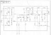

Capture3.JPG
 
Both idles are at 25mv and the dc balance is at 0mv. All four trim pots operated smoothly. I followed these directions:

1. no speaker load, don't bother with the 4.7k resistors, just turn off/down the volume control.
2. Adjust Vr1 for each channel to minimum (0v) voltage at the speaker terminals OR terminal 23 to ground.
3. 20 minute warm up
4. Adjust Vr3 for 25 mV between terminals 9 and 13
5. Readjust Vr1 for for each channel to minimum (0v) voltage at the speaker terminals
6.Check the 25mV reading - adjust as necessary
7. repeat from step #2 until no change is needed or observed.
 
It passes DBT. Here are the dc voltages from the power supply board, AWR-032. They are are spot on except pin 9

1 0
2 -16.4v
3 -24.9v
4 -13.0v
5 -42.1v
6 -56.3v
7 +55.5v
8 +42.4v
9 +39.7v (should be 35v)
10 +24.7v
11 +16.2v
 
Last edited:
I just pulled R24 (180ohm) on the power supply board and it was measuring 75ohm. I replaced it and now I get the correct voltage (+35v) at both AWR032 Pin 9 and AWM025 Pin 11. Still no relay click.
 
Re-look at the DC balance at the amp boards. Terminal 12 on each board.
It looks like the Balance is off, reading 81mV's on the left amp.
 
Re-look at the DC balance at the amp boards. Terminal 12 on each board.
It looks like the Balance is off, reading 81mV's on the left amp.

Both the left and right voltage on AWH-023 Pin 12 measures about 100mv at power on, then within a few seconds drops down to 0mv.
 
That eliminates DC on the speakers and incorrect rail voltages, time to check the protection circuit. Compare voltages to the schematic, should give you a clue or two as to what is wrong.
 
Here are my amp board voltages:

Right
1 +24.9v
2 0
3 0
4 0
5 0
6 -42.3v
7 0
8 +42.6V
9 +12.5mv
10 0
11 -42.3v
12 +0.6mv
13 -8.8mv
14 +42.2v

Left
1 +24.9v
2 0
3 0
4 0
5 0
6 -42.2v
7 0
8 +42.7v
9 +12.9mv
10 0
11 -42.5v
12 +0.3mv
13 -13.1mv
14 +42.6v
 
Voltages from the protection board (AWM-025C):

Q3: E -330mv, C +35.2v, B 0
Q4: E: -143mv, C +1.2v, B: +0.5v
Q5: E bounces between +2.3v and +4.0v, C +0.6v, B bounces between +1.7v and +4.0v
Q6: E 0v, C +3.3mv, B +0.6v
Q7: E 0v, C +35.1v, B +3.3mv
 
Q4 is holding things off. Collector of 1.2v
That keeps Q5 on, and Q6 on, which keeps C6 discharged. Which is protect disengage relay.
That's DC balance detect.... hmmm....

power amps
left
9 +12.5mv idle current read point, OK
10 0
11 -42.3v
12 +0.6mv amplifier output, OK
13 -8.8mv idle current read point, OK
right
9 +12.9mv idle current read point, OK
10 0
11 -42.5v
12 +0.3mv amplifier output, OK
13 -13.1mv idle current read point, OK

Power amps are blameless.....

First post's protection board voltages:
1 -81.3mv left channel input voltage, looks OK
2 -13.1v this is the -13v power input, to provide bias to the DC detector. It is OK
3 +0.7v right channel input voltage HMMM, THIS VOLTAGE IS NOT JUSTIFIED, IT DOES NOT MATCH IT'S SUPPOSED SOURCE, left channel amp pin 12.
4 0 ground for the board. OK.
5 -81.8mv left channel idle current read point
6 -81.3mv left channel idle current read point
7 -83.5mv right channel idle current read point
8 -85.1mv right channel idle current read point
9 +39.4v this is the transistor switched side of the relay coil, it will be at +39v when the relay is OFF, and about +10v when the relay IS ON and drawing power.
10 +39.5v this is the hot coil side of the relay power.
11 +39.4v this is the +35v power input, to run the board.
12 -3.4mv AC 7.5VAC input from the lighting circuit to determine turned on/turned off status.

The reason pin 9 is at 10 volts when the transistor is switched on, is that R28, 220 ohms 1 watt is in circuit -
the relay is only 24v on a 35v circuit, this soaks up the surplus 10v that would overheat the relay.


Ok, pin 3 protect voltage is 0.7v, that's enough to shut things down.
BUT
that is supposed to be the left channel pin 12 output (which would be +-idle current close on pins 9 & 13.

tl/dr:
Protection board's PIN 3's wire is mis-connected somewhere!!!
 
Thanks markthefixer and everyone else!

Good news: I found that the wire from the protection board pin 3 to pin 12 of the right amp board was disconnected and was hidden. I reconnected it.

Bad news: Still no relay click, however I have new protection board voltages:

1 +1.5mv
2 -12.9v
3 +0.7v
4 0
5 -11.8mv
6 +11.9mv
7 +11.9mv
8 -12.4mv
9 +35.2v
10 +35.2v
11 +35.2v
12 -3.4mv
 
Rereading the post from @fromnowon, I decided to replace these two transistors:

AWM-025-A Q3 2SC945 512-KSC1845FTA
AWM-025-A Q4 2SC945 512-KSC1845FTA

I now get a click from the relay! I get sound, terrible sound. But it works! Thanks everyone! I have more work to do.
 
Progress!
I'm curious if you've cleaned all the controls and switches yet. I mean really well, multiple times if necessary. You probably did but it wasn't mentioned.
 
Progress!
I'm curious if you've cleaned all the controls and switches yet. I mean really well, multiple times if necessary. You probably did but it wasn't mentioned.

Yep. I just finished cleaning all of the controls and replacing most of the caps and troublesome transistors. I didn't replace the main filter caps, but I got all the rest though. It's all buttoned up now and it sounds great!

E6sYj_WWQAYuv4w
 
Beautiful amp; congratulations on getting it working. I really like the SA-7100, 8100 and 9100 series.
 
Beautiful amp; congratulations on getting it working. I really like the SA-7100, 8100 and 9100 series.

Thanks. The 9100 is a pain to work on as I was constantly fighting with the wires. I didn't want to remove any wire wraps and I tried not flexing them too much. Of course, a few broke off. Accessing the two vertical equalizer boards was no fun. In addition to all of the recap/resto posts here, this page was helpful. http://www.alexandrugroza.ro/vintageaudio/content/pioneer_sa-9100/index.html
 
Back
Top Bottom