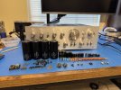
So I bought an SA-9500 II last summer. The seller didn't package it well and it arrived damaged. I had to replace the case, the face plate, and the function switch knob right off the bat. The function switch shaft was badly bent as well, but I was able to straighten it out at the cost of breaking one of the forks that hold the knob in place (sadness). I was able to get the function knob to hold securely though. An internal inspection revealed that two of the filter caps had popped on the underside. So I had to replace the filter caps as well. I replaced all four, just because.
I haven't used the amp much since I picked it up. Mostly I've been rotating between my Spec system, my SX-1050 and my SA-9900. I got bored last month though and decided to rebuild the 9500 II. Several of the caps I used in a previous 9500 II rebuild are no longer available so I selected replacements. Two of the caps that I ordered for this rebuild are not currently available and will need replacing if you use this BoM. The 512-KSC3503ESTU and 512-KSA1381ES transistors are no longer available, but I had a small supply on hand. I don't know what you'd replace them with.
I replaced the 2SA798 differential pairs on the amplifier boards with a small circuit board with a surface mount transistor package I bought from Affinity for Artifacts. I've been doing surface mount soldering on old Macintosh computers for a while now, so the differential pair kits weren't difficult to assemble. They seem to work very well. If anyone knows differently please let me know.
I replaced the function switch while I had the equalizer amp board out.
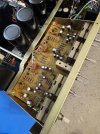
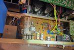
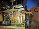
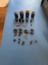
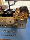
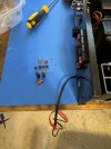
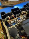
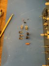
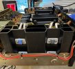
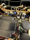
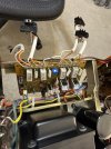
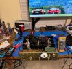
The rebuild went pretty smoothly. I enjoyed myself and took my time. The bias aligned easily and the dc offset is great. I've been running the amp for the past several days with no issues. I plan to use it for a few more weeks before calling it good. Here are some pics of the rebuild process.
Here's the BoM I used:
---------------------
Control Amp (AWG-045)
---------------------
AWG-045: C15: 4.7uF 50v CEANL: 667-EEU-FC1H4R7B 4.7uF 50v
AWG-045: C16: 4.7uF 50v CEANL: 667-EEU-FC1H4R7B 4.7uF 50v
AWG-045: C17: 4.7uF 50v CEANL: 667-EEU-FC1H4R7B 4.7uF 50v
AWG-045: C18: 4.7uF 50v CEANL: 667-EEU-FC1H4R7B 4.7uF 50v
AWG-045: C25: 4.7uF 50v CEANL: 667-EEU-FC1H4R7B 4.7uF 50v
AWG-045: C26: 4.7uF 50v CEANL: 667-EEU-FC1H4R7B 4.7uF 50v
AWG-045: C27: 4.7uF 50v CEANL: 667-EEU-FC1H4R7B 4.7uF 50v
AWG-045: C28: 4.7uF 50v CEANL: 667-EEU-FC1H4R7B 4.7uF 50v
AWG-045: C31: 100uF 16v CEANL: 647-UKL1E101KPDANA 100uF 25v
AWG-045: C32: 100uF 16v CEANL: 647-UKL1E101KPDANA 100uF 25v
AWG-045: C33: 4.7uF 50v CEANL: 667-EEU-FC1H4R7B 4.7uF 50v
AWG-045: C34: 4.7uF 50v CEANL: 667-EEU-FC1H4R7B 4.7uF 50v
AWG-045: C41: 4.7uF 50v CEANL: 667-EEU-FC1H4R7B 4.7uF 50v
AWG-045: C42: 4.7uF 50v CEANL: 667-EEU-FC1H4R7B 4.7uF 50v
AWG-045: C43: 4.7uF 50v CEANL: 667-EEU-FC1H4R7B 4.7uF 50v
AWG-045: C44: 4.7uF 50v CEANL: 667-EEU-FC1H4R7B 4.7uF 50v
AWG-045: C47: 100uF 16v CEANL: 647-UKL1E101KPDANA 100uF 25v
AWG-045: C48: 100uF 16v CEANL: 647-UKL1E101KPDANA 100uF 25v
AWG-045: C49: 4.7uF 50v CEANL: 667-EEU-FC1H4R7B 4.7uF 50v
AWG-045: C50: 4.7uF 50v CEANL: 667-EEU-FC1H4R7B 4.7uF 50v
AWG-045: C51: 100uF 35v CEA: 647-UPW1V101MPD 100uF 35v
AWG-045: C52: 100uF 35v CEA: 647-UPW1V101MPD 100uF 35v
AWG-045: C53: 100uF 35v CEA: 647-UPW1V101MPD 100uF 35v
AWG-045: C54: 100uF 35v CEA: 647-UPW1V101MPD 100uF 35v
Q1: 2SA640 ecb: 512-KSA992FBU ecb
Q2: 2SA640 ecb: 512-KSA992FBU ecb
Q3: 2SA640 ecb: 512-KSA992FBU ecb
Q4: 2SA640 ecb: 512-KSA992FBU ecb
Q5: 2SC1400 ecb: 512-KSC1845FTA ecb
Q6: 2SC1400 ecb: 512-KSC1845FTA ecb
Q7: 2SC1400 ecb: 512-KSC1845FTA ecb
Q8: 2SC1400 ecb: 512-KSC1845FTA ecb
Q9: 2SC1400 ecb: 512-KSC1845FTA ecb
Q10: 2SC1400 ecb: 512-KSC1845FTA ecb
--------------------------------------------------------------------------------------
Power Amp (AWH-052), times 2, as there are two power amp boards, one for each channel.
--------------------------------------------------------------------------------------
AWH-052: C4: 22uF 50v CEA: 667-EEU-FC1H220 22uF 50v
AWH-052: C5: 470uF 6.3v CEA: 647-UPW1A471MPD 470uF 10v
AWH-052: C15: 1uF 50v XXXX: 80-R82DC4100CK60J 1uF 63v (Kemet film)
Q1: 2SA798: Replaced with a small circuit board with a surface mount transistor package
Q2, Q3: 2SC1903 ecb: 512-KSC3503ESTU ecb (Had on hand, did not order)
Q4: 2SA898 ecb: 512-KSA1381ES ecb (Had on hand, did not order)
Q5: 2SD381 bce: 863-MJE15032G bce
Q6: 2SB536 bce: 863-MJE15033G bce
D1: 1S2473: 512-1N4148
D3, D4: W06A: 512-1N4004RLG
VR1: 100B: 3386H-1-101LF (Bourns 100ohm 10% Trimmer)
-------------------------
Switch Assembly (AWS-109)
-------------------------
AWS-109: C7: .68uF 35v XXXX: 505-MKS2.68/63/10 .68uF 63v (Wima film)
AWS-109: C8: .68uF 35v XXXX: 505-MKS2.68/63/10 .68uF 63v (Wima film)
AWS-109: C9: .22uF 10v XXXX: 505-MKS20.22/63/5 .22uF 63v (Wima film)
AWS-109: C10: .22uF 10v XXXX: 505-MKS20.22/63/5 .22uF 63v (Wima film)
AWS-109: C11: 330uF 6.8v CEA: 647-UPW1A331MPD 330uF 10v
AWS-109: C12: 330uF 6.8v CEA: 647-UPW1A331MPD 330uF 10v
AWS-109: C13: 100uF 16v CEAL: 647-UKL1E101KPDANA 100uF 25v
AWS-109: C14: 2.2uF 50v Unknown: 647-UPW1H2R2MDD 2.2uF 50v
AWS-109: C19: 330uF 80v CEA: 647-UPW2A331MHD 330uF 100v
AWS-109: C20: 330uF 80v CEA: 647-UPW2A331MHD 330uF 100v
AWS-109: C21: 220uF 63v CEA: 647-UPW1J221MPD6 220uF 63v
AWS-109: C22: 220uF 63v CEA: 647-UPW1J221MPD6 220uF 63v
AWS-109: C25: 47uF 16v CEA: 667-EEU-FC1V470 47uF 35v
AWS-109: C26: 47uF 16v CEA: 667-EEU-FC1V470 47uF 35v
AWS-109: C29: 47uF 35v CEA: 667-EEU-FC1V470 47uF 35v
AWS-109: C30: 47uF 35v CEA: 667-EEU-FC1V470 47uF 35v
AWS-109: C34: 3.3uF 50v CEA: 667-EEU-FC1H3R3B 3.3uF 50v
AWS-109: C35: 3.3uF 50v CEA: 667-EEU-FC1H3R3B 3.3uF 50v
Q1: 2SC869 bce: 512-KSC1845FTA ecb or 512-KSC2383YTA ecb
Q2: 2SC869 bce: 512-KSC1845FTA ecb or 512-KSC2383YTA ecb
Q3: 2SC945A bce: 512-KSC945CYTA ecb
Q4: 2SC945A bce: 512-KSC945CYTA ecb
Q5: 2SA733 ecb: 512-KSA992FTA ecb
Q6: 2SC945A bce: 512-KSC945CYTA ecb
Q7: 2SC1384 ecb: 512-KSC2690AYS ecb
Q8: 2SD526 bce: 863-MJE15032G
Q9: 2SB596 bce: 863-MJE15033G
Q10: 2SC1318 ecb: 512-KSC2383YTA ecb or 512-KSC2690AYS ecb
Q11: 2SA720 ecb: 512-KSA1013YBU ecb
Q12: 2SC1318 ecb: 512-KSC2383YTA ecb or 512-KSC2690AYS ecb
Q13: 2SA720 ecb: 512-KSA1013YBU ecb
Q14: 2SD356 bce: 863-MJE15032G bce
Q15: 2SC945 ecb: 512-KSC945CYTA ecb
D1-D8: SR3AM-8: 512-1N5404RLG
D9-D12: SR1K-8: 863-1N4004RLG
D13, D14: WZ-130: 512-1N4743ATR
D15, D16: 1S2473: 512-1N4148
D17-D21: 1S2472: 512-1N4148
D22-D25: 1S2473: 512-1N4148
-----------------------
Equalizer Amp (AWF-024)
-----------------------
AWF-024: C1: 1uF 50v XXXX: 80-R82DC4100CK60J 1uF 63v (Kemet film)
AWF-024: C2: 1uF 50v XXXX: 80-R82DC4100CK60J 1uF 63v (Kemet film)
AWF-024: C9: 470uF 6.3v CEA: 647-UPW1A471MPD 470uF 10v
AWF-024: C10: 470uF 6.3v CEA: 647-UPW1A471MPD 470uF 10v
AWF-024: C17: 3.3uF 50v CEA: 667-EEU-FC1H3R3B 3.3uF 50v
AWF-024: C18: 3.3uF 50v CEA: 667-EEU-FC1H3R3B 3.3uF 50v
AWF-024: C21: 4.7uF 25v (NP): 667-ECE-A1EN4R7U 4.7uF 25v
AWF-024: C22: 4.7uF 25v (NP): 667-ECE-A1EN4R7U 4.7uF 25v
AWF-024: C31: 47uF 35v CEA: 667-EEU-FC1V470 47uF 35v
AWF-024: C32: 47uF 35v CEA: 667-EEU-FC1V470 47uF 35v
AWF-024: C35: 47uF 35v CEA: 667-EEU-FC1V470 47uF 35v
Q1: 2SA906 bce: 512-KSA992FBU ecb
Q2: 2SA906 bce: 512-KSA992FBU ecb
Q3: 2SA906 bce: 512-KSA992FBU ecb
Q4: 2SA906 bce: 512-KSA992FBU ecb
Q5: 2SC1400 ecb: 512-KSC1845FTA ecb
Q6: 2SC1400 ecb: 512-KSC1845FTA ecb
Q7: 2SC1400 ecb: 512-KSC1845FTA ecb
Q8: 2SC1400 ecb: 512-KSC1845FTA ecb
Q9: 2SA750 ecb: 512-KSA992FBU ecb
Q10: 2SA750 ecb: 512-KSA992FBU ecb
-----------------
FILTER CAPACITORS
-----------------
C6, C7, C8, C9: 12000uf 63v: ALT22A153DE063 15000uf 63v
------------------
OUTPUT TRANSISTORS
------------------
Q1, Q2, Q5, Q6: 2SD588A bce - Did not replace
Q3, Q4, Q7, Q8: 2SB618A bce - Did not replace
---------------------
BOM
---------------------
667-EEU-FC1H4R7B | 16
647-UKL1E101KPDANA | 5
647-UPW1V101MPD | 4
667-EEU-FC1H220 | 2
647-UPW1A471MPD | 4
80-R82DC4100CK60J | 4
505-MKS2.68/63/10 | 2
505-MKS20.22/63/5 | 2
647-UPW1A331MPD | 2
647-UPW1H2R2MDD | 1
647-UHE2A331MHD | 2
647-UPW1J221MPD6 | 2
667-EEU-FC1V470 | 7
667-EEU-FC1H3R3B | 4
667-ECE-A1EN4R7U | 2
ALT22A153DE063 | 4
512-KSA1381ES | 2
512-KSC3503ESTU | 4
863-MJE15032G | 4
863-MJE15033G | 2
512-KSA1013YBU | 2
512-KSC2383YTA | 2
512-KSC2690AYS | 1
512-KSC945CYTA | 4
512-KSA992FBU | 10
512-KSC1845FTA | 12
512-1N4148 | 5
512-1N4004RLG | 4
512-1N5404RLG | 8
512-1N4743ATR | 2
3386H-1-101LF | 2
I haven't used the amp much since I picked it up. Mostly I've been rotating between my Spec system, my SX-1050 and my SA-9900. I got bored last month though and decided to rebuild the 9500 II. Several of the caps I used in a previous 9500 II rebuild are no longer available so I selected replacements. Two of the caps that I ordered for this rebuild are not currently available and will need replacing if you use this BoM. The 512-KSC3503ESTU and 512-KSA1381ES transistors are no longer available, but I had a small supply on hand. I don't know what you'd replace them with.
I replaced the 2SA798 differential pairs on the amplifier boards with a small circuit board with a surface mount transistor package I bought from Affinity for Artifacts. I've been doing surface mount soldering on old Macintosh computers for a while now, so the differential pair kits weren't difficult to assemble. They seem to work very well. If anyone knows differently please let me know.
I replaced the function switch while I had the equalizer amp board out.
The rebuild went pretty smoothly. I enjoyed myself and took my time. The bias aligned easily and the dc offset is great. I've been running the amp for the past several days with no issues. I plan to use it for a few more weeks before calling it good. Here are some pics of the rebuild process.
Here's the BoM I used:
---------------------
Control Amp (AWG-045)
---------------------
AWG-045: C15: 4.7uF 50v CEANL: 667-EEU-FC1H4R7B 4.7uF 50v
AWG-045: C16: 4.7uF 50v CEANL: 667-EEU-FC1H4R7B 4.7uF 50v
AWG-045: C17: 4.7uF 50v CEANL: 667-EEU-FC1H4R7B 4.7uF 50v
AWG-045: C18: 4.7uF 50v CEANL: 667-EEU-FC1H4R7B 4.7uF 50v
AWG-045: C25: 4.7uF 50v CEANL: 667-EEU-FC1H4R7B 4.7uF 50v
AWG-045: C26: 4.7uF 50v CEANL: 667-EEU-FC1H4R7B 4.7uF 50v
AWG-045: C27: 4.7uF 50v CEANL: 667-EEU-FC1H4R7B 4.7uF 50v
AWG-045: C28: 4.7uF 50v CEANL: 667-EEU-FC1H4R7B 4.7uF 50v
AWG-045: C31: 100uF 16v CEANL: 647-UKL1E101KPDANA 100uF 25v
AWG-045: C32: 100uF 16v CEANL: 647-UKL1E101KPDANA 100uF 25v
AWG-045: C33: 4.7uF 50v CEANL: 667-EEU-FC1H4R7B 4.7uF 50v
AWG-045: C34: 4.7uF 50v CEANL: 667-EEU-FC1H4R7B 4.7uF 50v
AWG-045: C41: 4.7uF 50v CEANL: 667-EEU-FC1H4R7B 4.7uF 50v
AWG-045: C42: 4.7uF 50v CEANL: 667-EEU-FC1H4R7B 4.7uF 50v
AWG-045: C43: 4.7uF 50v CEANL: 667-EEU-FC1H4R7B 4.7uF 50v
AWG-045: C44: 4.7uF 50v CEANL: 667-EEU-FC1H4R7B 4.7uF 50v
AWG-045: C47: 100uF 16v CEANL: 647-UKL1E101KPDANA 100uF 25v
AWG-045: C48: 100uF 16v CEANL: 647-UKL1E101KPDANA 100uF 25v
AWG-045: C49: 4.7uF 50v CEANL: 667-EEU-FC1H4R7B 4.7uF 50v
AWG-045: C50: 4.7uF 50v CEANL: 667-EEU-FC1H4R7B 4.7uF 50v
AWG-045: C51: 100uF 35v CEA: 647-UPW1V101MPD 100uF 35v
AWG-045: C52: 100uF 35v CEA: 647-UPW1V101MPD 100uF 35v
AWG-045: C53: 100uF 35v CEA: 647-UPW1V101MPD 100uF 35v
AWG-045: C54: 100uF 35v CEA: 647-UPW1V101MPD 100uF 35v
Q1: 2SA640 ecb: 512-KSA992FBU ecb
Q2: 2SA640 ecb: 512-KSA992FBU ecb
Q3: 2SA640 ecb: 512-KSA992FBU ecb
Q4: 2SA640 ecb: 512-KSA992FBU ecb
Q5: 2SC1400 ecb: 512-KSC1845FTA ecb
Q6: 2SC1400 ecb: 512-KSC1845FTA ecb
Q7: 2SC1400 ecb: 512-KSC1845FTA ecb
Q8: 2SC1400 ecb: 512-KSC1845FTA ecb
Q9: 2SC1400 ecb: 512-KSC1845FTA ecb
Q10: 2SC1400 ecb: 512-KSC1845FTA ecb
--------------------------------------------------------------------------------------
Power Amp (AWH-052), times 2, as there are two power amp boards, one for each channel.
--------------------------------------------------------------------------------------
AWH-052: C4: 22uF 50v CEA: 667-EEU-FC1H220 22uF 50v
AWH-052: C5: 470uF 6.3v CEA: 647-UPW1A471MPD 470uF 10v
AWH-052: C15: 1uF 50v XXXX: 80-R82DC4100CK60J 1uF 63v (Kemet film)
Q1: 2SA798: Replaced with a small circuit board with a surface mount transistor package
Q2, Q3: 2SC1903 ecb: 512-KSC3503ESTU ecb (Had on hand, did not order)
Q4: 2SA898 ecb: 512-KSA1381ES ecb (Had on hand, did not order)
Q5: 2SD381 bce: 863-MJE15032G bce
Q6: 2SB536 bce: 863-MJE15033G bce
D1: 1S2473: 512-1N4148
D3, D4: W06A: 512-1N4004RLG
VR1: 100B: 3386H-1-101LF (Bourns 100ohm 10% Trimmer)
-------------------------
Switch Assembly (AWS-109)
-------------------------
AWS-109: C7: .68uF 35v XXXX: 505-MKS2.68/63/10 .68uF 63v (Wima film)
AWS-109: C8: .68uF 35v XXXX: 505-MKS2.68/63/10 .68uF 63v (Wima film)
AWS-109: C9: .22uF 10v XXXX: 505-MKS20.22/63/5 .22uF 63v (Wima film)
AWS-109: C10: .22uF 10v XXXX: 505-MKS20.22/63/5 .22uF 63v (Wima film)
AWS-109: C11: 330uF 6.8v CEA: 647-UPW1A331MPD 330uF 10v
AWS-109: C12: 330uF 6.8v CEA: 647-UPW1A331MPD 330uF 10v
AWS-109: C13: 100uF 16v CEAL: 647-UKL1E101KPDANA 100uF 25v
AWS-109: C14: 2.2uF 50v Unknown: 647-UPW1H2R2MDD 2.2uF 50v
AWS-109: C19: 330uF 80v CEA: 647-UPW2A331MHD 330uF 100v
AWS-109: C20: 330uF 80v CEA: 647-UPW2A331MHD 330uF 100v
AWS-109: C21: 220uF 63v CEA: 647-UPW1J221MPD6 220uF 63v
AWS-109: C22: 220uF 63v CEA: 647-UPW1J221MPD6 220uF 63v
AWS-109: C25: 47uF 16v CEA: 667-EEU-FC1V470 47uF 35v
AWS-109: C26: 47uF 16v CEA: 667-EEU-FC1V470 47uF 35v
AWS-109: C29: 47uF 35v CEA: 667-EEU-FC1V470 47uF 35v
AWS-109: C30: 47uF 35v CEA: 667-EEU-FC1V470 47uF 35v
AWS-109: C34: 3.3uF 50v CEA: 667-EEU-FC1H3R3B 3.3uF 50v
AWS-109: C35: 3.3uF 50v CEA: 667-EEU-FC1H3R3B 3.3uF 50v
Q1: 2SC869 bce: 512-KSC1845FTA ecb or 512-KSC2383YTA ecb
Q2: 2SC869 bce: 512-KSC1845FTA ecb or 512-KSC2383YTA ecb
Q3: 2SC945A bce: 512-KSC945CYTA ecb
Q4: 2SC945A bce: 512-KSC945CYTA ecb
Q5: 2SA733 ecb: 512-KSA992FTA ecb
Q6: 2SC945A bce: 512-KSC945CYTA ecb
Q7: 2SC1384 ecb: 512-KSC2690AYS ecb
Q8: 2SD526 bce: 863-MJE15032G
Q9: 2SB596 bce: 863-MJE15033G
Q10: 2SC1318 ecb: 512-KSC2383YTA ecb or 512-KSC2690AYS ecb
Q11: 2SA720 ecb: 512-KSA1013YBU ecb
Q12: 2SC1318 ecb: 512-KSC2383YTA ecb or 512-KSC2690AYS ecb
Q13: 2SA720 ecb: 512-KSA1013YBU ecb
Q14: 2SD356 bce: 863-MJE15032G bce
Q15: 2SC945 ecb: 512-KSC945CYTA ecb
D1-D8: SR3AM-8: 512-1N5404RLG
D9-D12: SR1K-8: 863-1N4004RLG
D13, D14: WZ-130: 512-1N4743ATR
D15, D16: 1S2473: 512-1N4148
D17-D21: 1S2472: 512-1N4148
D22-D25: 1S2473: 512-1N4148
-----------------------
Equalizer Amp (AWF-024)
-----------------------
AWF-024: C1: 1uF 50v XXXX: 80-R82DC4100CK60J 1uF 63v (Kemet film)
AWF-024: C2: 1uF 50v XXXX: 80-R82DC4100CK60J 1uF 63v (Kemet film)
AWF-024: C9: 470uF 6.3v CEA: 647-UPW1A471MPD 470uF 10v
AWF-024: C10: 470uF 6.3v CEA: 647-UPW1A471MPD 470uF 10v
AWF-024: C17: 3.3uF 50v CEA: 667-EEU-FC1H3R3B 3.3uF 50v
AWF-024: C18: 3.3uF 50v CEA: 667-EEU-FC1H3R3B 3.3uF 50v
AWF-024: C21: 4.7uF 25v (NP): 667-ECE-A1EN4R7U 4.7uF 25v
AWF-024: C22: 4.7uF 25v (NP): 667-ECE-A1EN4R7U 4.7uF 25v
AWF-024: C31: 47uF 35v CEA: 667-EEU-FC1V470 47uF 35v
AWF-024: C32: 47uF 35v CEA: 667-EEU-FC1V470 47uF 35v
AWF-024: C35: 47uF 35v CEA: 667-EEU-FC1V470 47uF 35v
Q1: 2SA906 bce: 512-KSA992FBU ecb
Q2: 2SA906 bce: 512-KSA992FBU ecb
Q3: 2SA906 bce: 512-KSA992FBU ecb
Q4: 2SA906 bce: 512-KSA992FBU ecb
Q5: 2SC1400 ecb: 512-KSC1845FTA ecb
Q6: 2SC1400 ecb: 512-KSC1845FTA ecb
Q7: 2SC1400 ecb: 512-KSC1845FTA ecb
Q8: 2SC1400 ecb: 512-KSC1845FTA ecb
Q9: 2SA750 ecb: 512-KSA992FBU ecb
Q10: 2SA750 ecb: 512-KSA992FBU ecb
-----------------
FILTER CAPACITORS
-----------------
C6, C7, C8, C9: 12000uf 63v: ALT22A153DE063 15000uf 63v
------------------
OUTPUT TRANSISTORS
------------------
Q1, Q2, Q5, Q6: 2SD588A bce - Did not replace
Q3, Q4, Q7, Q8: 2SB618A bce - Did not replace
---------------------
BOM
---------------------
667-EEU-FC1H4R7B | 16
647-UKL1E101KPDANA | 5
647-UPW1V101MPD | 4
667-EEU-FC1H220 | 2
647-UPW1A471MPD | 4
80-R82DC4100CK60J | 4
505-MKS2.68/63/10 | 2
505-MKS20.22/63/5 | 2
647-UPW1A331MPD | 2
647-UPW1H2R2MDD | 1
647-UHE2A331MHD | 2
647-UPW1J221MPD6 | 2
667-EEU-FC1V470 | 7
667-EEU-FC1H3R3B | 4
667-ECE-A1EN4R7U | 2
ALT22A153DE063 | 4
512-KSA1381ES | 2
512-KSC3503ESTU | 4
863-MJE15032G | 4
863-MJE15033G | 2
512-KSA1013YBU | 2
512-KSC2383YTA | 2
512-KSC2690AYS | 1
512-KSC945CYTA | 4
512-KSA992FBU | 10
512-KSC1845FTA | 12
512-1N4148 | 5
512-1N4004RLG | 4
512-1N5404RLG | 8
512-1N4743ATR | 2
3386H-1-101LF | 2
Last edited: