• The move to the new server is done. There are some software and database maintenance updates in process. This has us passing the hat around to help out. We appreciate any donations. Seriously, even a dollar helps. The payment page may be found here - https://www.audiokarma.org/support.html

SA-9500 II stuck in protection

I was thinking of seeing if TO-3p leads would fit in the batwing socket connections, and a single mounting hole drilled (tapped or with through bolt/screw) to mount it.

step 1: mount the transistor, making sure it is isolated electrically from the heat sink using a mica insulator

step 2: make the connections to the emitter base and collector.

one thought to discuss, the to-3p / to-247 etc mounted on the INNER face of the heat sink (through a pre-existing hole), socket discarded and euro type screw connectors tie the transistor and the wires together (sort of like what was done on the sx-3900).
 
I was researching a little and www.briarsfield-hifi.co.uk did a nice job using 2STA1962 and 2STC5242.

IMG_3053_1600_2.jpg


mouser links 1 and 2
 
yup, looks like 1 hole drilled per transistor.

not wild about the solder job at the pins tho...

I'm a bit nuts, on any I would now do, I would enlarge that slot to fit the green connector shown below, and on the transistor leads make a 90 degree bend going inwards through the slot and slip the green connector onto the leads from behind. Fair warning, those green things are about 2 bucks apiece...

That picture is how we fix the sx-3800, sx-3900, sx-d5000, sx-d7000 duff sockets.

attachment.php
 
That picture is how we fix the sx-3800, sx-3900, sx-d5000, sx-d7000 duff sockets.

Mark,

That looks really clean. So after I wire-up the new transistors, is there a specific start-up sequence to limit the chances of frying something?

Do you think the transistors will be the extent of my problem?

Would you replace the output transistors for both channels or just the four in the channel that I know are bad?

thanks again,
David
 
some purists do all, for symmetry. I really don't expect there to be an audible difference, but I am a near purist, and since I am doing work on other peoples equipment,I do both channels - I don't want somebody with really well trained ears to hear a difference. Or even to look for and maybe THINK they hear a difference.

Realistically, There will be a bit more "robustness" to the repaired channel with the more powerful transistors. Meaning the unaltered channel would be the first to pop.

Yes there is a LOT we will talk about before power is reapplied - including DBT discussions, Idle current "teasing out the dragon" testing while ON the DBT and all that.
 
With the output transisters removed, can I turn on the amp to check the DC offset?

Should I check for any other failed devices?
 
yes, that's what all this was for in post #11

Insulate the sockets (plastic bags?) and try turning on the unit again and see if the fuse blows now.

When it turns on, if possible without endangering the sockets insulation, check the c8 and c9 voltages.

Then go to the power amp assembly and measure and post all the pin's voltages. IF you can't reach them, measure the voltages at the empty transistor sockets, that will tell me most of what I need to know. Look for burned components on the board.
 
When it turns on, if possible without endangering the sockets insulation, check the c8 and c9 voltages.

Then go to the power amp assembly and measure and post all the pin's voltages. IF you can't reach them, measure the voltages at the empty transistor sockets, that will tell me most of what I need to know. Look for burned components on the board.

Mark,

I'm retaking the measurements. I realized when I went to bed last night that I hadn't replaced the fuse before taking the measurements. :bash:
 
Last edited:
Ok, I think you have figured out that C8 and C9 are not powered due to FU1 being blown.

When it turns on, if possible without endangering the sockets insulation, check the c8 and c9 voltages.

Then go to the power amp assembly and measure and post all the pin's voltages. IF you can't reach them, measure the voltages at the empty transistor sockets, that will tell me most of what I need to know. Look for burned components on the board.

Hi Mark,

Here are the measurements:

C8 -52.5V
C9 52.5V

40 -6.0mv
41 -2.5mv
42 0.1mv
43 -6.5mv
44 -7.0mv
45 3.5mv
46 5.0mv
47 52.5V
48 -52.2V
49 51.9V
50 -51.8V
51 60.0mv
52 0.0mv
53 66.5mv
54 66.6mv
55 66.6mv
56 66.6mv

thanks,
David
 
Ouch, that's the sound of crossed eyes and mental whiplash.

I have no idea where you got those pin numbers from. :confused:

I was expecting to see a awh-052 power amplifier board. Pins 1 through 23, with pins 1 - 12 across the top edge being the most important.
 
Ouch, that's the sound of crossed eyes and mental whiplash.

I have no idea where you got those pin numbers from. :confused:

I was expecting to see a awh-052 power amplifier board. Pins 1 through 23, with pins 1 - 12 across the top edge being the most important.

Are these measurements referenced from ground or am I looking for the idle current as referenced to the output terminal (pin 17?)
 
Ouch, that's the sound of crossed eyes and mental whiplash.

I have no idea where you got those pin numbers from. :confused:

I was expecting to see a awh-052 power amplifier board. Pins 1 through 23, with pins 1 - 12 across the top edge being the most important.

Pin readings from awh-052, referenced to ground:

1 -0.1mv
2 -0.5mv
3 -0.8mv
4 0.0mv
5 0.0mv
6 0.0mv
7 -0.7mv
8 -0.4mv
9 0.0mv
10 0.0mv
11 0.0mv
12 0.0mv
13 0.0mv
14 -0.6mv
15 1.6mv
16 -0.1mv
17 0.0mv
18 -0.1mv
19 -0.0mv
20 -0.1mv
21 -0.1mv
22 -0.2mv
23 -0.1mv
24 -0.0mv

Thanks :)
 
Uh oh, either you weren't actually grounded, your meter or leads have a break, or that is the most complete blackout of a live board I have ever seen.

list what model and make your meter is, what range you were using and which jacks on the meter the leads are plugged in to.

dumb question, was the power on? it should have been. The meter set to DC volts. The model and make will allow me to figure out if it auto ranges (switches gears to appropriate voltage readings / ranges) or whether you need to switch the ranges yourself...
 
list what model and make your meter is, what range you were using and which jacks on the meter the leads are plugged in to.

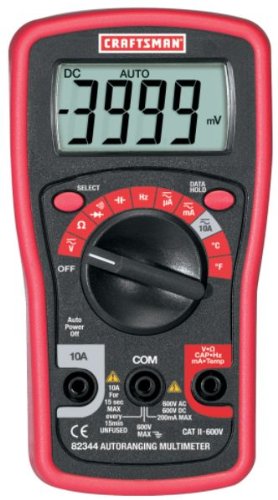
The meter in question is a Craftsman 82344, auto-ranging.
51E0kcJlrKL.jpg


The meter was set to read DC volts. It was reading correctly as I had just taken readings on C6, C7, C8 and C9 to confirm they were getting voltage.

Before I took readings on pins 1-24, I double checked the bags protecting the output sockets. One of the bags had come off so I turned off the amp before putting the bag back on. When I went to put the socket back in the bag, one of the wire-wrapped leads touched the heat sink and arced -- of course it was the 57V lead. Even though the amp was turned off, I realized after-the-fact that the caps were still charged.

Gathering my wits, I unplugged the amp, bagged the socket and secured all of them with rubber bands this time. Before I took the pin measurements, I checked the fuses, plugged the amp back in and checked C6, C7, C8 and C9 voltages.

Even though the arc was between the cap and the heatsink, is it still possible that I fried something? I'm starting to think this amp and I have a very bad relationship. :sigh:
 
Well, in that case, the unit being on,

pin 20 should have had +48v regulated power
pin 20 should have had -48v regulated power
pin 14 should have had +46v UNregulated power
pin 13 should have had -46v UNregulated power
pins 2 & 5 are connected directly to pin 14's +46v
pins 8 & 11 are connected directly to pin 13's -46v

so there's some additional work to be done. Start by removing and testing EVERY fuse.
 
Well, in that case, the unit being on,

pin 20 should have had +48v regulated power
pin 20 should have had -48v regulated power
pin 14 should have had +46v UNregulated power
pin 13 should have had -46v UNregulated power
pins 2 & 5 are connected directly to pin 14's +46v
pins 8 & 11 are connected directly to pin 13's -46v

so there's some additional work to be done. Start by removing and testing EVERY fuse.
Mark, here are my pin readings:

1 .966V
2 51.6V
3 -8.0mv
4 .966V
5 51.7V
6 -9.0mv
7 -.877V
8 -51.7V
9 -9.2mv
10 -.875V
11 -51.8V
12 -8.0mv

13 -51V
14 51V
15 -7.2mv
16 -10.1mv
17 -9.9mv
18 -0.0mv
19 47.4V
20 47.4V
21 -47.1V
22 -0.4mv
23 -0.2mv

Thanks :)
 
Ok, these are pretty good readings, I want you to find the idle current pot VR1, right between pins 6 and 7 and turn it down to zero ohms, fully CCW, then repeat the readings, pins 1,4, 7 & 10 will read a bit lower voltage. Then I will know it's ready for new outputs. The voltages on pins 1,4, 7 & 10 are a bit high, and may be why the outputs eventually failed.

when we get to the point where we are setting idle current, the 5.1k resistor and 8 ohm resistor mentioned in the manual are NOT needed.
 
Ok, these are pretty good readings, I want you to find the idle current pot VR1, right between pins 6 and 7 and turn it down to zero ohms, fully CCW, then repeat the readings, pins 1,4, 7 & 10 will read a bit lower voltage. Then I will know it's ready for new outputs. The voltages on pins 1,4, 7 & 10 are a bit high, and may be why the outputs eventually failed.

when we get to the point where we are setting idle current, the 5.1k resistor and 8 ohm resistor mentioned in the manual are NOT needed.

Will do. Thanks Mark.
 
Back
Top Bottom