• The move to the new server is done. There are some software and database maintenance updates in process. This has us passing the hat around to help out. We appreciate any donations. Seriously, even a dollar helps. The payment page may be found here - https://www.audiokarma.org/support.html

SAE Mark 1B Preamp Repair

vaathi

baski
Subscriber
Good Morning AKers
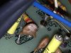
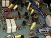
I picked up non working SAE preamp which was in good cosmetic condition thinking it will work after few squirts of DeOxit. It powers up and that is all it does. I connected my Iphone and connected the Preamp to Marantz 2230. I don't hear any sound. I played with all the possible knobs there is. Only sound I did here was a thud when i switched on and off the EQ defeat button. I did see corrosion inside in one of the transistor and 22uf/15V (yellow one in the first pic) funny looking cap has skin peeling off. I have attached couple of pics of board. I dont know where to start to debug since this will be my first debug of electronic issue. I would appreciate your insight and help to figure this out.

--baski
 

Attachments

  • IMG_2705-001.jpg
    IMG_2705-001.jpg
    73.5 KB · Views: 195
  • IMG_2716.jpg
    IMG_2716.jpg
    60.5 KB · Views: 191
  • IMG_2714.jpg
    IMG_2714.jpg
    90.3 KB · Views: 175
  • IMG_2715-001.jpg
    IMG_2715-001.jpg
    119.3 KB · Views: 183
  • IMG_2710.jpg
    IMG_2710.jpg
    78.3 KB · Views: 173
Register to hide this ad
Well, you need a schematic of the unit, and what I'd do, is a very close inspection, at the 2nd pict you have a ceramic cap disconnected (this is not the main fault for sure), and that transistor looks weird to me, I'd measure it or replace it.

Check the power supply, that every line has the right voltage. You need the schematic to do this.

Then, with the schematic, you need to trace the signal. You can measure AC voltage (audio signal is AC) at different amplifier stages, playing a test tone, and check where that signal is lost.

Another trick is to extract the signal to a second amp, with a probe and a capacitor (to block DC going to the second amp), and "listen" to the signal, follow the signal path until the signal is lost.

But check the basic first: visual inspection, and voltages reaching every board.

Measure DC voltage across the large filter caps. You should have something near the voltage rating of the cap. For example, at a 50V capacitor, you could have something like 35 to 45 Volt.

BE VERY CAREFUL WHEN MEASURING INSIDE A UNIT WITH THE POWER ON !! FIX THE BLACK PROBE TO GROUND (AMP CHASSIS USUALLY) AND MEASURE WITH THE RED PROBE, WITH ONE HAND AT YOUR BACK OR IN YOUR POCKET.

I PREFER MINI GRABBERS, FIX THEM WITH THE UNIT OFF, AND POWER-ON WITHOUT TOUCHING ANYTHING.
 
Last edited:
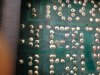
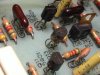
Also inspect under the pcb for corosion and use a magnify glass to inspect the solder joints. In photo #4, on the left corner, there is a big metal transistor with corosion that needs to clear and check. On the right side of the same photo there is a transistor (q53) that looks not good.
Make sure the volume on the iphone is not very low!
Take your time with a big cup of coffee!! :yes:
 
Had a Mk1B for many years; a very versatile preamp.

When you get it singing, you'll be happy!

Best of luck!
 
Only the scope out works when I power it on. Jim from SAEs site helped me with schematics. I did not have time to go over it in detail. I will do it tonight and post more information on the possible issue. As far now, I need to order a good DMM from a-z site to get going.
 
I have a very cheap multimeter, very useful, with capacitance meter. And another a bit more expensive (cheap anyway) with Hfe measurement.

I'd get one with capacitance AND Hfe measurement.
 
Sure. I will look for some decent meter. I am surrounded by Frys Electronics in bay area... I opened the top cover and I saw lot of corrosion in the PCBs. I don't know if they are the reason for failure. I have attached some pics of PCB.
 

Attachments

  • Picture 002.jpg
    Picture 002.jpg
    103.6 KB · Views: 104
  • Picture 003.jpg
    Picture 003.jpg
    88 KB · Views: 83
  • Picture 007.jpg
    Picture 007.jpg
    79.2 KB · Views: 86
I have an UNI-T UT10, very handy, I use this one most of the time because it's auto-range and very small, it measures capacitors too, but not Amperes (current) or hFE (transistors gain). It measures diodes and transistor voltage drops.

So I've got a cheap UYIGAO UA9205N , that measures current and hFE gain.

I use the small one all the time.

Regarding the corrosion, it could be or not the source of the problem. It could short some traces, or damage some of them cutting the trace or the components leads. You need to clean it, and check for continuity of the traces. Check associated components too.
 
I got the Amprobe 240 and the schematics. From initial diag it looks like problem most probably will be in the Line AMP section.
 
Last edited:
I'd say, first, locate all those disconnected components, and try to replace them. Do a visual inspection. Do that visual inspection AGAIN. Many problems can be detected with a visual inspection.

Then, with the schematic, measure DC voltage at the filter caps. to see if you have the right voltages. Then keep measuring voltages further in the circuit. But start at the power supply. The unit won't work without power.

Everytime we say "measure voltage", it means, negative probe of your multimeter to ground (usually, the chassis is "ground"), so you can attach one probe to the chassis, and measure with the red probe at the suggested points, so you can check the voltage sign.

So, negative to ground, and positive to all the points you can check against schematic.

BE CAREFUL, DON'T RISK ANYTHING, MEASURE WITH ONE HAND AND THE OTHER HAND AT YOUR BACK, INSULATE THE PROBE LEAVING JUST THE VERY END OF THE TIP EXPOSED SO YOU DON'T TOUCH OTHER COMPONENTS WHILE MEASURING.

Read the schematic first, so you know what voltage to expect at each point.

If you want, sen me a PM with a link to the schematic. If you bought the schematic from some vendor, I think it's fair to not share it, and support the people who keeps all those manuals for us.
 
elnaldo.. I got the schematics from Jim from SAE site. I can send it over to you...
 
Last edited:
Ok. In the meantime, start reading the schematic, locating the parts in the PCB, check those disconnected components, read the voltages in the schematic, the start point will be the power supply, fuses, and supply voltage.
 
1st, read the service manual hints, it points you to some possible problems and solutions.

If you can, disconnect the boards from the power supply, and check you have the voltages stated on the schematic.

You must have 45V DC and 20V DC at the power supply output. Adjust the power supply pot until you measure 45V at the output.

BE CAREFUL !

HIGH VOLTAGES THERE, DON'T SHORT ANYTHING, DON'T RISK EVEN A BIT, BE SURE YOUR PROBES ARE STEADY AND WON'T SLIP SHORTING COMPONENTS. IF A POINT IS HARD TO ACCESS, LOOK FOR ANOTHER POINT ELECTRICALLY CONNECTED, WITH AN EASIER ACCESS.
 
Last edited:
Does anyone have the Schematics for the SAE MARK 1B. I have not been able to get ahold of Jim from SAE site.

Any help would be great. Hoping to fix mine soon!

Thanks,

Joseph
 
Hi Craig:
I am looking for a MK1B Schematic. It's the older version. Would you have access to one?
Brad Wilson
 
The earliest is the MKI with the six paddle switches across the middle. The B and the M were the next versions. I do not have and have not been able to find any info on the MKI. :(

Craig
 
Back
Top Bottom