Greetings all,
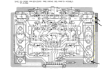
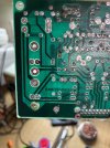
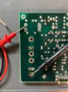
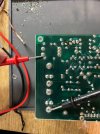
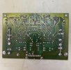
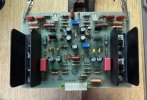
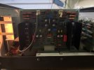
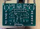
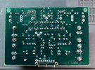
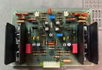
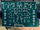
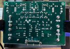
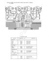
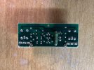
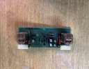
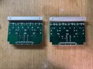
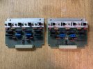
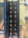
I am in the process of repairing and restoring an SAE 2500 Pre-Drive Board. In taking out the screws to the hear sink, one of the copper rings separated from the pcb (see !MG_1070). It is the bottom screw hole in the photograph and is the bottom hole of the q4 transistor. In looking at the spec sheet (also attached), although there is no direct trace between it, there should be continuity between that heat sink screw and the outside nodes of R31 and R36. There is continuity between those 3 nodes on the twin pre-drive board in the amplifier. IMG_1072 is a photo with my multimeter prongs pointing to the three nodes, and IMG_1073 and 1074 are photos of the twin board for comparison.
As I mentioned before, in looking at the board and the spec sheet, there's no direct trace between these. So my first question is - do I need to re-establish continuity between these nodes despite the fact that they're not connect via trace line? I suspect the answer will be yes, which leads to the second question: how would you go about doing that? My initial thought would be to jumper the bottom screw node with the outside nodes of the two resistors, but let me know if there is other, preferable methods. If using a jumper is the way to go, would you use one wire and solder it to both the resistors on the one side, or two jumper cables, one to each resistor (the latter seems like overkill but thought I'd ask).
Any assistance or answers are welcome. Thanks in advance.
Jack
I am in the process of repairing and restoring an SAE 2500 Pre-Drive Board. In taking out the screws to the hear sink, one of the copper rings separated from the pcb (see !MG_1070). It is the bottom screw hole in the photograph and is the bottom hole of the q4 transistor. In looking at the spec sheet (also attached), although there is no direct trace between it, there should be continuity between that heat sink screw and the outside nodes of R31 and R36. There is continuity between those 3 nodes on the twin pre-drive board in the amplifier. IMG_1072 is a photo with my multimeter prongs pointing to the three nodes, and IMG_1073 and 1074 are photos of the twin board for comparison.
As I mentioned before, in looking at the board and the spec sheet, there's no direct trace between these. So my first question is - do I need to re-establish continuity between these nodes despite the fact that they're not connect via trace line? I suspect the answer will be yes, which leads to the second question: how would you go about doing that? My initial thought would be to jumper the bottom screw node with the outside nodes of the two resistors, but let me know if there is other, preferable methods. If using a jumper is the way to go, would you use one wire and solder it to both the resistors on the one side, or two jumper cables, one to each resistor (the latter seems like overkill but thought I'd ask).
Any assistance or answers are welcome. Thanks in advance.
Jack