• Please note that Audiokarma will be offline briefly for updates early on Monday morning, September 28th.

SAE Two R9-No sound, want to confirm it's toast or?

MtnAudio

AK Subscriber
Subscriber
I got this from a friends collection of old units he had in his garage. It worked fine.
I know, not a REAL SAE but my nephew needed a receiver so I gave it to him to use.
I'm not a tech and I am ignorant other than basic check outs and soldering in dial lights so please forgive the questions.
He set it up and no sound. Brought it back and sure enough no sound, all the lights work except no LED lights on Amp output meter.

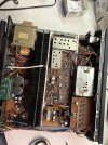
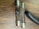
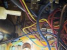
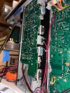
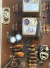
I just got around to checking it and both fuses are blown and looks like a component leakage on a trimmer? of some sort.

Not worth a lot so paying for a repair is out unless you all tell me different.
Fuses show 125V 7amp. They don't indicate a Slow Blow fuse as far as I can see.
I would normally figure he had it cranked and plugged it in or something and just replace the fuses but is that component a safety problem and or indicate a bigger problem?
 

Attachments

  • IMG_2141.jpeg
    IMG_2141.jpeg
    137.4 KB · Views: 63
  • IMG_2140.jpeg
    IMG_2140.jpeg
    165.7 KB · Views: 53
  • IMG_2142.jpeg
    IMG_2142.jpeg
    180.3 KB · Views: 47
  • IMG_2145.jpeg
    IMG_2145.jpeg
    188.5 KB · Views: 43
  • IMG_2144.jpeg
    IMG_2144.jpeg
    134.2 KB · Views: 48
  • IMG_2146.jpeg
    IMG_2146.jpeg
    112.1 KB · Views: 61
Register to hide this ad
The things I will venture to guess are that the residue on the board came from outside the receiver, not from any component on the board; and, that area of the board is part of the tuner function, and extremely unlikely to have anything to do with the fuses blowing.

A less-well-informed guess, if this receiver uses STK modules in the power amp, is that one of the STK output modules has shorted.

If you have (or can make) a "dim bulb tester", you could try installing fuses and powering up with very little risk of causing any further damage or safety concerns. Info about "DBT"s is easily found by searching AK.
 
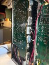
Are these 4 black and blue components the ones to test and how do I test in place?
These transistors are labeled NEC D745 R04B
 

Attachments

  • IMG_2160.jpeg
    IMG_2160.jpeg
    279.9 KB · Views: 25
Last edited:
Are these 4 black and blue components the ones to test and how do I test in place?
These transistors are labeled NEC D745 R04B

Well, they are the output transistors, and are among the prime suspects for a fuse-blowing situation.

The ones labeled D745 are 2SD745, an NPN transistor. You can find a datasheet for those, and it will identify which leads are base, emitter, and collector. I think you've misread the other label, but the others will be PNP transistors and will have the same lead layout as the NPNs.

In this situation, I think the most useful test you can make in-circuit is to check resistance between the emitter and collector leads. If it is close to zero ohms, it is pretty sure that the transistor itself is shorted. Other in-circuit tests may be less definitive.
 
Thanks.
If those are shorted is the likely scenario that the transistor failed or something up or downstream caused them to short?
 
If those are shorted is the likely scenario that the transistor failed or something up or downstream caused them to short?

Either scenario is possible, I'm afraid.

If you find emitter-collector shorts in the output transistors, but the base-emitter junctions are intact (can be checked with the "diode test" mode that most modern meters have), then I'm pretty sure that you can simply disconnect the collectors to do further checking. The collectors are the center leads, and it looks like it should be easy enough to desolder those leads and bend them away from the board.

With collectors disconnected, you can try powering up, with no speakers connected, and preferably using a DBT. Oh, and you would first install fuses.

With luck, the result would be that the receiver would power up sort of normally and come out of protection (assuming it has a conventional protection relay circuit). Then, you would want to check for any excessive DC voltage at the outputs of the power amplifiers. The emitter leads of the output transistors are a physically convenient place to probe for this, and are electrically close enough. The DC voltages on the emitters should be near to zero, say less than 0.1VDC of either + or - polarity.

If the aforegoing looks good, you can even try listening - through headphones only and at low volume - to make sure the rest of the signal paths are OK.
 
Both Output Transistors D745 and B705 on the same side are shorted Emitter-Collector legs
Other side of amp both measure as an open.

Diode test On the failed Transistors
-B705 Base to Emitter and Collector .184
-D745 Base tp Emitter and Collector 0.94
 

Attachments

  • IMG_2226.jpeg
    IMG_2226.jpeg
    168 KB · Views: 4
-B705 Base to Emitter and Collector .184
-D745 Base tp Emitter and Collector 0.94

Those readings are not what I'd expect if the B-E junctions were OK. You could remove the transistors and check the B-E junctions out-of-circuit, but it's not clear where that would lead - though I guess if you find that the B-E junctions still test bad out-of-circuit, it makes it more likely that there is additional damage "upstream".

If you want to go further with this, I think you're going to need to find a schematic somehow.
 
Last edited:
If you want to go further with this, I think you're going to need to find a schematic somehow.

I am not at all sure, but the power amp circuits in the SAE Two A7 integrated amp might be close enough to the R9's to make the A7 schematic a usable surrogate. You can find some sort of info on the A7 on elektrotanya.com.

If the R9 really is much like the A7, then the B-E junctions of the output transistors are paralleled with resistors of something like 150 ohms, which could account for the readings obtained with the diode-mode test. That could be checked with conventional ohmmeter readings after the output transistors have been removed.
 
I'm not going further with it as I'd be getting over my head and have many other projects ahead of it.
Looking at Ebay sales I see the prices on these have increased over the last few years.
I'll either take it to a shop I use for a look see or sell it for parts repair.

Thanks everyone for your time and advice
 
Back
Top Bottom