• The move to the new server is done. There are some software and database maintenance updates in process. This has us passing the hat around to help out. We appreciate any donations. Seriously, even a dollar helps. The payment page may be found here - https://www.audiokarma.org/support.html

Safety relay pioneer sx 780/790

jeryve

New Member
Hello everyone,

I'm having this problem with the safety (speaker output) relay of my pioneer sx790 (EUROPEAN 220 VOLT). I got it recently and the previous owner told me that the safety relay
would not "kick in" as one powers the receiver up.

Looking at the poor solder joints someone had been messing around with it

I took off the relay and noticed that it had only 6 "legs" on it.
2 were cut off (it used to be 8) on the outer "switch side" of the relay.

It reads TYPE MS2 24VDC DEC 046 on the relay cover.
I would like to know if this is an original relay and if there is an replacement relay for it.

I sure hope someone can help me out.

Greetings JERYVE

P.S.
Sorry for my english grammar I'm from Holland and not used doing this on a dayly bases.
 
Register to hide this ad
Jeryve; Your English is a hell of a lot better than my Dutch. Welcome to the board.

Here's a pic of the one in my 790. It's a US model so the voltage is 48V, where your's is 24v. Could be the relay is dirty, although that seems not to be happening too much with the 780's/790's I've been reading of on here. Clean the contacts CAREFULLY, and put it back in. Sounds like yours is original.

Get the Service Manual in the PIONEER DATABASE.

most common problems that I can remember.
1.) Bad Solder Joints. Especially around the voltage regulators. If you look at the relay from the front of the unit, the regulators are 3 transistor looking components with HEATSINKS on them just to the right and behind the relay. They heat up a lot and the joints crack. CHECK THEM WITH THE UNIT UNPLUGGED as the heatsinks are HOT electrically. Then Check all of the boards for cold or cracked joints.

2.) Plug it in and Take voltage readings on the STK modules (these are your output transistors). Make sure the ends of your probe is insulated except for the very end of the tip. Reading left to right are pins 1 thru 10.Take readings on all pins. And Post them. Mark the Fixer may stop by and look.

3.) Take Voltage readings of the voltage supply. Flaky supply readings can cause the relay NOT TO kick in. Regulated and non regulated supplys. Write down the pin # and the reading.

4.) Bad/dirty contacts on the speaker switches. CLEAN CLEAN CLEAN!!!With De-Oxit and Faderlube.

5.) Clean the fuses and fuse holders.

6.) Just for curiousity check the DC OFFSET @ the spkr terminals. Use mA scales on the multimeter. Post Results.


The board underside at the relay is the 2nd picture. In the Bottom Left corner surrounded by the wires are 10 pins arranged in a "U" Shape

. .
....
....

These are the pins for the relay. What you are probably seeing on the bottom of the relay are the factory cut off's to fit the board. That's what I'm thinking, unless someone has a better theory or explanation.


Larry
 
Last edited:
Yes, that is a factory relay.

Look at the solder joints under the three power transistors in a row, with the metal fins screwed on. The joints tend to crack as they heat and cool.

After cleaning up the solder, and if it still doesn't work, measure the voltages of all three legs on all three transistors and post them. measure from left to right when the lettering on the transistor is facing you.

This post should help:
You don't, that picture shows a receiver that has NOT been cooked - no heat discoloration. Thus that change is unnecessary and risky.

If you don't find cracked solder joints under those three transistor / heat sink assemblies, then you need to take some voltage measurements.

Insulate all but the very tip of the red dmm probe (for when it slips - so it doesn't short to anything else - instant component death...)and connect the black probe to a bare metal part of the chassis.

Then measure the voltages on all three leads of all three transistors, left to right. The part number lettering on the transistor must face you for the correct left to right, and include those part numbers with each voltage measurement set.

Then measure the voltages on each power output module's pins: 1,2,3,8,9,0 (the three leftmost and rightmost pins on each module).
 
Hello again everyone,

First I want to thank you guys for all the great advice.
Second I got rid of one problem being the sx 790, the print had been damaged beyond repair so I sold it to this guy as a "donor receiver ".
But now I have a new problem being an sx 750 with a relay that also won't work (print seems to be just fine).
I sure would like some help on this one as I am determined to get this baby going !

Greetings to you all from a hot Holland!

P.S. There is also this pioneer tx 710 for sale around here, is it any good ?
 
Last edited:
Hello everyone,

I'm having this problem with the safety (speaker output) relay of my pioneer sx790 (EUROPEAN 220 VOLT). I got it recently and the previous owner told me that the safety relay
would not "kick in" as one powers the receiver up.

Looking at the poor solder joints someone had been messing around with it

I took off the relay and noticed that it had only 6 "legs" on it.
2 were cut off (it used to be 8) on the outer "switch side" of the relay.

It reads TYPE MS2 24VDC DEC 046 on the relay cover.
I would like to know if this is an original relay and if there is an replacement relay for it.
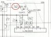
Sounds to me like someone has replaced the original 48V relay with a 24V relay.

Need to check out the value for R321. Supposed to be 620 ohms with a 48V relay. With a 24V relay, this 620 ohm resistor will burn up.
 

Attachments

  • 780_Relay_ckt.jpg
    780_Relay_ckt.jpg
    45.9 KB · Views: 36
Back
Top Bottom