I'm troubleshooting a Kenwood KR-5600 (see also: this thread) where I recapped and replaced some transistors on the power amp board. Now I have very weak audio at the left speaker but seemingly good audio volume in the right channel.
To troubleshoot, I first traced the signal in the working channel to have something to compare to.* To do this, I:
I searched all over this site and the whole web and didn't find anything that really explained exactly how to connect the signal generator to the input. I just see more general statements like "connect the signal generator to an aux input" without much detail. Do people cut off the ends of RCA cables and connect to the bare wires? If I want to test both channels at the same time, do I feed the same signal generator signal to each RCA channel? I figure I can make a little jig of some kind to mount the RCA cables on to keep them organized and away from each other.
* I'm not totally convinced that the right channel is working properly (I don't measure any gain after the first stage), but at least the signal is going all the way through.
To troubleshoot, I first traced the signal in the working channel to have something to compare to.* To do this, I:
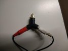
- Connected the positive end of the signal generator cable (alligator clip) to the tip of an RCA cable, and wrapped electricians tape around the sleeve to prevent an accidental short (I should probably cut off the jack on one end and connect directly to the wire).
- I connected the black signal generator clip to chassis ground on the receiver.
- I disconnected the ground clips from the scope probes.
- Set the signal generator to 1KHz at 1Vpp (I also tried lower voltages but this seemed to produce a better signal to trace).
- Connected one scope probe to the positive end of an 8-ohm dummy load and observed the amplified signal.
- Plugged the receiver into a dim-bulb tester and turned it on.
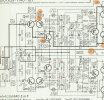
- Connected the other probe to various spots in the power amp signal path and was able to trace the signal everywhere I thought I should see it (I think...).
- Powered down.
- Moved RCA cable from right to left aux input.
- Moved first scope probe to left dummy load
- Powered on with DBT
- DBT went bright and relay shut off power to the amp.
I searched all over this site and the whole web and didn't find anything that really explained exactly how to connect the signal generator to the input. I just see more general statements like "connect the signal generator to an aux input" without much detail. Do people cut off the ends of RCA cables and connect to the bare wires? If I want to test both channels at the same time, do I feed the same signal generator signal to each RCA channel? I figure I can make a little jig of some kind to mount the RCA cables on to keep them organized and away from each other.
* I'm not totally convinced that the right channel is working properly (I don't measure any gain after the first stage), but at least the signal is going all the way through.