Racingh11
Super Member
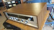
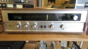
I was checking out a Sansui 210 receiver. It is a single sided power supply with the lower voltage tied to chassis ground. It is rectified into a 1000uF 50V capacitor that shows the negative lead going to ground in the schematic. On the board, the negative lead is not connected to anything, and the board is marked "NC" in the copper next to it. Checking voltage across the cap shows about 5 volts DC. Checking from chassis to positive lead is 45V. From chassis to negative lead is about 0.3V. I'm guessing the impedance of the meter is loading that during testing and giving the results that don't really make sense. Why would anyone have a power cap only connected at one terminal. There is no copper or wires running to the cap on the front side.