• The move to the new server is done. There are some software and database maintenance updates in process. This has us passing the hat around to help out. We appreciate any donations. Seriously, even a dollar helps. The payment page may be found here - https://www.audiokarma.org/support.html

Sansui 3000a Restoration, question on mods

tubmyk2

AK Subscriber
Subscriber
I am about to start restoring a ‘somewhat’ working 3000a that appears to be mostly original. I have a couple questions related to modifications and the known service bulletin.

Looking at the protection caps below, they would appear factory if not for the (assumed) date codes:
F6FC7AE2-6B9E-4B89-885D-ECDA63DAF4CB.jpeg 8226C199-F066-4E06-8C7D-137F6E634620.jpeg E5587BFB-D19A-4B94-AE1A-FFA18E5EB918.jpeg

I’m not yet familiar with the 3000a but after looking over the service bulletin I do see that this is a modification; just done a bit differently from what is written out. If I were to keep this layout and replace what is here, is it acceptable? Or do I need to up the capacitance?

Also, if anyone has a preferred resource for documentation on anything else, please let me know. I don’t want to start this one until I know I have all my facts straight.
 
Register to hide this ad
Those caps look like they may be toast (leaked their guts, out gassed). Looks like a quality mod, possibly done in the factory. Mine looked different. It is preferable to find and repair known problems before embarking on a full re-cap or rebuild. Or you run the risk of inserting a new problem and complicate the repair. But since those look shot you could start with them. Build yourself a DBT (Dim Bulb Tester) to use when powering on to limit current until you are confident there are no major shorts etc. Test after each board or section is recapped.

Here is a factory mod: Looks like maybe yours someone used 2 polarized 1000uf caps in series to create 1 non-polorized 2000uf cap for each one? I would study that closely to understand exactly what is going on there. Edit: Is that Red wire connected to the other white wire? Supposed to be only blue and white wires to each separate cap.
upload_2022-12-17_12-9-18.jpeg
 
I used 1,000µF, 35V non-polars with complete success. The newer ones are so small that they fit almost anywhere.

That actually does look like a factory alteration, or from a service center which did good quality work using the factory"upgrade" mod parts.
 
I used 1,000µF, 35V non-polars with complete success. The newer ones are so small that they fit almost anywhere.

That actually does look like a factory alteration, or from a service center which did good quality work using the factory"upgrade" mod parts.

That's good to know. Yes, I figured it was at least done professionally back in the day (based on the date codes on the caps) so then i can just replace like for like.
 
The modifications involve several components. It is fairly well documented in various places, including: https://www.hifiengine.com/manual_library/sansui/3000.shtml

Verify that all the indicated components have been altered and/or added.

Sansui3000AModifiedOutputCircuit.jpg
 
I have restored a few Sansui 3000a’s and have several waiting to be restored. This the most common situation seen when it comes a receiver that had a service center “back in the day” perform the direct coupling, resistor, diode, fuse factory service bulletin modification CE-007-A for the 3000a.

9C1FC417-FDB9-4FA2-8301-ACBEB716EA1D.jpeg FF8CBE68-5D89-47C1-B433-9494FDDB3023.jpeg 3963DE03-3998-480A-8A00-916E035DC1A1.jpeg 3CC11E62-8D16-44D4-BE28-D787E1F4F7D1.jpeg D78854A9-7BFD-46EB-92AC-D57B10E2C4DC.jpeg E846799E-DB75-4365-B54F-7A4DA6842D34.jpeg E35E02B8-2CC1-42A6-9ABD-FB8E2A113C0A.jpeg 66A649F5-9AC9-4936-B69C-51CCD055E9E6.jpeg 6553E15D-6FC4-4E2D-B779-9FFA3D779F2C.jpeg 90DFA363-1CC5-40A0-AB1A-6E8D22F70E80.jpeg
 
Something to watch out for with the 3000A: at least on mine, instead of just soldering the components to the PCB through-hole and cutting off the leads, they folded the leads down against the traces and soldered them in place. On top of that, the traces don't have great adhesion to the boards after 50 years. Removing any components from the boards that need to come off can be a PITA.
 
One thing I would do first is make sure you're not gonna smoke the speakers you might hook up to them. I like the dbt idea to get started. You might make sure you don't have high dc at the speaker outputs. Once you get inside, take a look around, see what's been done and not, then at some point, look into checking that bias.

Whether you use the current method or emitter voltage method, make sure your trim pots VR801, 2, 3 and 4 are working. If you can measure across them for ohms, it shouldn't just be locked on at a fixed value of 15 or 10 ohms. That would make it impossible to set the bias, balance things out.

That's all I have for now. Hope you can enjoy this thing once you get it going. Touchy little rcvr but monster sound imo.
 
So I fixed a 3000a for a friend this weekend, tuned my own up due to a strange sound from the left channel, so discovered the bias was not behaving, so that seemed to help the overall sound.

So there was this other receiver I've had from a few years ago, a used 300a I'd bought from the Bay that never seemed to do anything, no sound either channel. I can recall trying to bias this one and at least one of the channels I couldn't get the current below about 220 mA. I worked on the output part of the amp, tried to find component failures on the pre and driver boards, nothing. So this weekend after having success with the other two rcvrs, I put it back on the bench and did a full on re-bias. Oh, the first thing I did is replaced a couple of trim pots, VR 801 and 802 iirc. I was then able to get the 80ma on all four. But, no sound at all, including from the headphones. I took to it again this morning because I goofed, found a diode on the floor that I'd missed, for the left channel I guess. I put it back together, no luck. For some weird reason, I decided to replace the burned out lamp on for the Protection circuit, the red one. Next thing I know it, I have music coming from the right channel, and I don't mean just noise, it sounds fantastic. But no left channel. I'm pretty happy I've gotten this far, but ummm no sound from headphones, if I crank it up all the way and move the balance pot to full left, I hear the faintest music, not distorted, but a tiny signal coming from that left speaker. Swapped speaker leads on the unit, so not the wring or interconnects.

I'm assuming a miswiring somewhere, a bad resoldering on my part, some weird thing like a misadjustment on the protection board? I did replace the 458 just for GPs. I guess it could be a broken wire somewhere, but no hum, etc.
 
Many modern day transistors do have different pin outs that the OE from the 60s. Might double check that on that dead channel?
 
Many modern day transistors do have different pin outs that the OE from the 60s. Might double check that on that dead channel?
Ok, sounds good.

When I look at signal with a scope on the collector of the negatively going signal, I see just DC on the dead one and modulation on the good one, for whatever that's worth.

I just wish I could find a good starting point to go through the system. I will try and look at voltages at test points given in the hard to see amp schematic and see if I can find something, while also comparing to the other channel.
 
Greetings,
I am working a Sansui 30000A. Serial Number is 228031919.. It has had no mods what so ever. I smoked a speaker when I first got it.
I have rebuilt all of the outputs. I have completely rebuilt the TRZ output diver board. I encounted a open diode in doing that board.
My question is does anybody have an accurate descriptionw, diagram of hat I need to modify.
The drawing I have shows adding a 100 Ohm resistor to the base circuit of the main outputs.on one side and adding a .3 Ohm on the other...
A misprint I assume ?
I have a drawing but it appears to have several errors as stated above ,and is mostly illegible
I repaired a 3000A I got off of the bay and it sounds really good for a 57 year old unit !
I bought it because I saw, in the pictures, it had been modified. I was hoping to use it as a model so I would know what to do.
Any help is greatly appreciated.
George
The speaker protection mod includes the following:

four 10 ohm, ½ watt resistors to be placed at the output transistor bases.
four 1 ohm, 3 watt resistors to take the place of the .3Ω emitter resistors.
four 2A quick acting fuses to replace the 4A fuses.
eight 1N4002 diodes to replace the eight diodes on the output board.
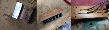
six 1000µf 35v bipolar electrolytic capacitors (three for each channel).

Screenshot (1064).png


I mounted the six electrolytic caps to a piece of wood flooring I had with wires long enough to go to the impedance switch and to also be wired to the spot highlighted in the circled area above. I mounted the board with nylon stand-offs over the bolts.

IMG_20210714_105346651_BURST001.jpg
IMG_20210714_120440267_BURST001.jpg
IMG_20210714_120448512.jpg
 
Awesome !
Exactly what I was looking for !
Thank you
George
When you go to connect the caps up, one wire from a group of 3 will be wired to the center post of the impedance switch. The wire that was there is pulled off and connected to the other wire of the same group of 3 caps you just built.
Same for the other channel. One wire to the other center post of the impedance switch and the other wire from that other group of 3 caps go to the wire you pulled off the switch.

IMG_20231010_131329679.jpg

IMG_20231012_103118680.jpg

IMG_20231010_151114475.jpg

IMG_20231010_211152149_HDR.jpg
 
Last edited:
I Have replaced all of the associated wiring with silicone wiring, and installed the 100 ohm resistors in the wires leading to the Base of the 4 outputs. I heat shrunk the connections, and left the resistors bodies visible . I replaced all 4 of TO-3 Output Xistors and sockets with the new wiring and new 1 Ohm Emitter resistors.
Rounding up the all the parts was a PITA.
I am still unsure of the cap additions...

The 3000A, I got off the Bay had 2 giant can 1000 Mfd caps. Looks factory. Emitter Resistors were 1 ohm. Diodes on the driver board had been replaced. didn't notice the 100 ohm Base resistors. I didn't realize they were on the back of the driver board.so I didn't look there. I did some lamp work, repaired the volume control , fader lubed the pots. Cleaned up it and it came out real nice.
Sounds great for a 57 year old stereo.
I would love to source 2, 4700 non polarized caps @ 35 vdc.
But I think they are made of unobtanium !
Thanks for all the great info
George
Lots of info in this thread:
https://www.audiokarma.org/forums/index.php?threads/my-sansui-3000a-restoration.1028651/
 
Back
Top Bottom