• The move to the new server is done. There are some software and database maintenance updates in process. This has us passing the hat around to help out. We appreciate any donations. Seriously, even a dollar helps. The payment page may be found here - https://www.audiokarma.org/support.html

Sansui 5050 Output Transistors

davehewitt12

New Member
Hello AK!

I have a 5050 I am getting back to working order. A transistor that is failed, and having trouble finding a new set of TO-66 transistors to replace the originals. I did not see any in the hugely helpful transistor list from a few years back (though it did help getting my 317 working again!) Open for suggestions! Thanks

-Dave
 
Register to hide this ad
TO-66 transistors are long obsolete, however plastic TO-220 transistors were designed to be dimensionally compatible with the old TO-66 types. Transistor substitution look-ups should be intelligent enough to suggest the TO-220 parts. The one thing you do lose is 'the look' some people are very attached to the look of a row of metal cased transistors on a chassis for example. Personally I was never that impressed with the look of TO-66 case transistors, much preferring the TO-3 style ones which are also becoming harder to find now.

BTW: Welcome to AK and the 'Exclusively Sansui' sub forum!
 
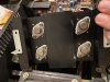
2sc1445, 2sa765. The amp has previous repairs done to it, so I cannot be certain they are the originals to the unit.
 

Attachments

  • IMG_2065.jpg
    IMG_2065.jpg
    83.8 KB · Views: 116
At some point during production Sansui upgraded the power supply board. Early production used F-2648 power supply board. Later production had a F-2701. They probably changed the output transistors at the same time. This is the kind of stuff we can document in the Serial number database. Please check to see which power supply board you have and post your serial number.

Thanks!

- Pete
 
My 5050 has blown the 2sc1445/2sa765 transistors an the 0.15 amp fuses. What would have caused that? Where can I find equivalent transistors? I'll post my serial numbers to match the F-2701 board.
 
2sc1445/2sa765 transistors. F-2701. 857091662.

Also blown outputs, drivers, bias transistor, .15A fuse, 6.8 ohm resistors on one side. Swapped with MJE15030Y and 15031Y. There is some oscillation super-imposed over a low level hum happening at the output when I power it up. When the relay kicks in the oscillation stops. This is with no load. Only monitored with a scope. 0 volts at the output. Continues to blow components when attempting to adj bias. Don't read any voltage drop across the emitter resistors. Am I measuring bias in the wrong place? Is it across one emitter resistor or both? I was measuring across both. Maybe thats my problem? ?????
 
[QUOTE = "Way San, publicación: 15083011, miembro: 337062"] Transistores 2sc1445 / 2sa765. F-2701. 857091662.

También salidas fundidas, controladores, transistor de polarización, fusible de .15A, resistencias de 6,8 ohmios en un lado. Intercambiado con MJE15030Y y 15031Y. Hay una oscilación superpuesta sobre un zumbido de bajo nivel en la salida cuando lo enciendo. Cuando el relé se activa, la oscilación se detiene. Esto es sin carga. Solo monitoreado con un alcance. 0 voltios en la salida. Continúa soplando componentes al intentar ajustar el sesgo. No lea ninguna caída de voltaje en las resistencias del emisor. ¿Estoy midiendo el sesgo en el lugar equivocado? ¿Se encuentra en una resistencia de emisor o en ambas? Estaba midiendo a través de ambos. ¿Quizás ese es mi problema? ?????[/CITA]
https://audiokarma.org/forums/index.php?threads/shorted-6060.826787/
 
Finally repaired this after blowing the outputs several times. The bias trimmers were replaced but I blew outputs in one channel whenever I tried to adjust the trimmers. This last time, I set the trimmers to the middle and left them alone. Did the bulb tests, direct AC, audio test, power test. All OK now.
 
Finally repaired this after blowing the outputs several times. The bias trimmers were replaced but I blew outputs in one channel whenever I tried to adjust the trimmers. This last time, I set the trimmers to the middle and left them alone. Did the bulb tests, direct AC, audio test, power test. All OK now.
The reason you had all those issues is the transistors you used as replacements have three times the transition frequency of the original transistors.
So the amplifier is going into self oscillation and destroying itself.
You need to look at the output on the scope and check for stability.
I would not, at this point assume everything is fine.
 
Back
Top Bottom