• The move to the new server is done. There are some software and database maintenance updates in process. This has us passing the hat around to help out. We appreciate any donations. Seriously, even a dollar helps. The payment page may be found here - https://www.audiokarma.org/support.html

Sansui 5050 total rebuild

Vtince

New Member
Hey all, recently picked up a Sansui 5050. It was in pretty rough shape, but complete. I decided to make this my side project and see if I can get it up and running.

I've meticulously replaced all the capacitors, diodes, fuse resistors, transistors and more on all the boards, with the exception of the output transistors (list of all components I replaced in below digikey links)

So now everything is back together. Plug the 5050 to a DBT, and DBT to wall, then I go to power on the 5050, bulb stays off (good sign), but I don't hear any relay click or anything. Multimeter on the leads going into unit reads 120vAC which means the cord is supplying power to the 5050, but now I'm not sure if the transformer is working?

Setting multimeter on vDC, I measure the Purple wires (+) coming out of the transformer and to chassis (-), and I get nothing, like only 0.2 mv. Am I doing this right? schematics shows 2 Purple wires with one showing (24.8v) and the other 24.8v.

Anyway hope someone can help a newbie out and let me know what I can do to check if there is power coming out of transformer.


I've compiled these list on Digikey and should be a complete list of what to replace on the 5050. (Hopefully this will help someone who is rebuilding one also)

F-2590: https://www.digikey.com/en/mylists/list/G6ZQFLOAXX
Phono: https://www.digikey.com/en/mylists/list/MT5CEU5PWD
Tone: https://www.digikey.com/en/mylists/list/M9E590IVI9
F-2700: https://www.digikey.com/en/mylists/list/9G4LRLHLNB
F-2701: https://www.digikey.com/en/mylists/list/Y7F38Z0DE6
F-2647: https://www.digikey.com/en/mylists/list/BIZIORS47E
Filter Caps: https://www.digikey.com/en/mylists/list/R1ILSWOZAZ


Thanks all, much appreciated!
 
Register to hide this ad
Hi,

Re the measurement of the purple wires from the secondary of the transformer, you need to have the multimeter set to measure AC Volts, the bridge rectifier converts the AC voltage to DC on the output side of the rectifier.

Cheers
John

PS - Welcome to AK!
 
Thanks,

Both Purple = 24.13v
Both Brown = 34.68v
White = 6.81v

Wooo so power transformer is working! Now no relay click....
 
I tried adjusting bias per the service manual, but I get no readings. Am I able to adjust bias with relay not clicking. Or does relays need to click before we can adjust bias?
 
I got my 5050 fixed last week. It sounds pretty good with new caps. The 5050 and 6060 share some boards and the manuals are not the best. I spent a few days looking at forums because I could not find any defective parts while rebuilding the 2700,2701 and 2647 boards. Relay kicked in the whole time. I checked all the fuse resistors and all tested good except I missed the one on the 2646 tone board. R601 and it was open. I checked the 2644 phono board and R601 fuse resistor was red hot. Rebuilt the tone board and 601 resistor. Found cap C08 was backwards from schematic. I thought that may be the issue with the 601 fuse resistor. I mark all the caps with a black dot toward the front before I pull them. Fired it up and it started working. Adjusted the bias and then rebuilt the phono board. R601 was not hot anymore, not even warm.
Look up the 12 fuse resistors, 6-220. 4-6.8. 2- 1.8. There are pictures too. Check the fuse resistors first. The relay must click or you wont get bias voltage. New transistors would need to be flipped.
I normally test the DC voltage on the power transistor case to ground first thing to see if anything is blown. The transformer is AC voltage converted to DC voltage. If you get about 33 volts on the power transistors, your transformer should be good.
You should never replace a bunch of parts first. Get it working first, too many variables now. One bad solder joint can trip you up.
The parts list is good but the Filter caps need about 25mm lead spacing.
I'm listening to mine now. Going to put a new walnut veneer on it and maybe new transistors. I believe this one sat for a long time broke and has low mileage.
Good luck.
 
I tried adjusting bias per the service manual, but I get no readings. Am I able to adjust bias with relay not clicking. Or does relays need to click before we can adjust bias?
Best to sort out cause of failed relay click, ie, high dc offset or... Measure dc voltage at the emitter resistor to GND, (same resistors as per bias, measure either position) repeat for other channel. Alternative could measure dc offset at relay. Expect less than 100mV. xxVolts would point to failed output or driver transistor or...
 
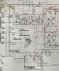
Ok did some multimeter checks and found that the brown wires from transform still both measure 32v after the R613 and R612 resistors. But, when I follow the schematics to the F-2701 board, I get very low voltage reading at around 2vAC at the pins, shouldn’t it still read 32v?

see attached:
circled in red = described above
Bottom marking from purple wires all checks out good voltages
 

Attachments

  • 25F0DE07-6A53-4CF6-B043-6BC4277FDEA0.jpeg
    25F0DE07-6A53-4CF6-B043-6BC4277FDEA0.jpeg
    177.3 KB · Views: 36
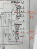
Also measured the emitter resistors and values are shown in photo, is this the correct place to measure?
 

Attachments

  • 1ED743B2-45FB-48B1-9CE0-51C2CD8F51F0.jpeg
    1ED743B2-45FB-48B1-9CE0-51C2CD8F51F0.jpeg
    155.8 KB · Views: 46
Also measured the emitter resistors and values are shown in photo, is this the correct place to measure?
Yep, perfect, measure between the emitter resistors. You need to measure dc voltage not AC. The 0.005, 0.007 would be great numbers if Vdc.
 
Ok did some multimeter checks and found that the brown wires from transform still both measure 32v after the R613 and R612 resistors. But, when I follow the schematics to the F-2701 board, I get very low voltage reading at around 2vAC at the pins, shouldn’t it still read 32v?
The mains supply is AC. The transformer converts mains AC to lower voltage AC. The rectifier/diode bridge corverts the AC into full wave rectifier (google for pix) The main filter caps convert the full wave rectified into something approaching a DC waveform, ie, a DC component with a small ripple wave. Measurements in the amp should generally be on the DC scale unless you are troubleshooting issues like hums and want to measure the ripple. Measure Vdc at main filters.
 
Anyway the DC measurement are:

-1.337VDC
-1.330VDC

yep, that's too high and will trip protection. Possibly an issue with the differential pair TR01, TR03 (left) and TR02, TR04(right channel). Have these been replaced? My schematic has these as 2SA726, these have a history of going noisy and should be replaced, KSA992, buy about 20 since you need matched pairs, ie, need to measure the hfe/beta and match within 5 or so.
 
Thanks for the help mbz,

I have replaced TR01, 02, 03, 04 on the F-2647 board with KSA992FBTA (https://www.digikey.com/en/products/detail/onsemi/KSA992FBTA/3163196).
Could it be the Output transistors? I have MJE15032G and MJE15033G handy.

Hi,

Just to confirm - when you replaced the 2SA726 transistors with the KSA992, did you confirm the difference in pin outs between these. The KSA has a different pin out to the 2SA726. With the flat face of the transistor package facing you, and the leads pointing down, the 2SA726 pin out is base, collector, emitter reading from left to right. The KSA992 pin out is emitter, collector, base. This means that the KSA992 needs to be oriented 180 degrees compared to the 2SA992 (collector is the centre lead, and the emitter and base leads are swapped)

Cheers
John
 
Yup, made sure to install in reverse and doublechecked with the datasheet for the KSA992 for pin outs.

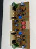
I’ve attached a photo of the F-2647 board here
 

Attachments

  • 8EC35224-1908-4557-8362-16C1AE2B6885.jpeg
    8EC35224-1908-4557-8362-16C1AE2B6885.jpeg
    103.4 KB · Views: 64
  • image.jpg
    image.jpg
    96.7 KB · Views: 62
The mains supply is AC. The transformer converts mains AC to lower voltage AC. The rectifier/diode bridge corverts the AC into full wave rectifier (google for pix) The main filter caps convert the full wave rectified into something approaching a DC waveform, ie, a DC component with a small ripple wave. Measurements in the amp should generally be on the DC scale unless you are troubleshooting issues like hums and want to measure the ripple. Measure Vdc at main filters.

Thanks, I understand a bit more. Now, since the AC input into the rectifier/diode bridge is coming from the mains, shouldn't it read 32VAC? voltmeter on mains is 32v, voltmeter after resistor is 32v, then it goes to F-2700 board via header pins, which voltmeter now reads 2v. Is this even possible?

See photo, Red dots are where I measured voltage to chassis ground.
 

Attachments

  • Screen Shot 2023-03-31 at 10.28.01 PM.png
    Screen Shot 2023-03-31 at 10.28.01 PM.png
    289.4 KB · Views: 40
Could it be the Output transistors? I have MJE15032G and MJE15033G handy.
Doubtful that the outputs are the cause of the dc offset so I wouldn't rush in that direction.
The red dots/2VAC is wrong and may be the cause of your dc offset. Power off/unplug the unit and resistance check between R612 and the corresponding red dot, repeat for R613 and red dot, expect 0.4ohms(ie near short). Check wires, solder connections,,,
EDIT Verify that R612, R613 measure 2.2ohms or abouts (2.6-2.8ohms?)
 
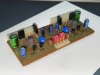
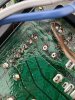
Soooo while checking the traces, I found a hairline crack in the board that runs through it. I’m going to bridge repair and report back after. See photo!!
 

Attachments

  • ACC881E1-2508-412D-94AD-BEF1E73AF796.jpeg
    ACC881E1-2508-412D-94AD-BEF1E73AF796.jpeg
    180.1 KB · Views: 59
  • Like
Reactions: mbz
After repairing the crack, the relay is clicking over and its working!!!!

I was now able adjust bias to:
14.8mV
14.9mV

Measuring Center or emitter resistors to chassis ground:
21.6mV
21.8mV


Now just need to clean the pots, as I hear some static.

Thanks for all those that helped, I learned a lot along the way.
 
Spoke too soon, played music for about 30mins, turned off unit, then turned it back on and now NO click....
 
Back
Top Bottom