• The move to the new server is done. There are some software and database maintenance updates in process. This has us passing the hat around to help out. We appreciate any donations. Seriously, even a dollar helps. The payment page may be found here - https://www.audiokarma.org/support.html

Sansui 7000 restoration issues

Oscar76

AK Subscriber
Subscriber
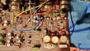
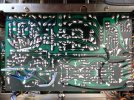
Good evening all. I recently purchased a Sansui 7000 that is in good condition so I decided to restore this old girl. The first board that I started on is the tone control board. I found that someone had purposely cut the traces between the 3 50v 220uF capacitors and the resistors that connector to them. They then ran jumpers between some of the destinations that the traces would have done but did not connect everything that was once connected. I have attached two photos of this for comment or explanation. I don't know if this was a factory job where they found an error and this was their correction or is this someones idea of obtaining a more desired sound. Everyone feel free to express your thoughts. As far as I am concerned there are no wrong answers since I don't have a glue. The first photo shows the traces that have been cut and the second picture is the 3 capacitors and the resistors and 50v 1uF caps that should have been connected together.
Have good evening all.
 

Attachments

  • IMG20230918200615.jpg
    IMG20230918200615.jpg
    123.4 KB · Views: 57
  • IMG20230918200925.jpg
    IMG20230918200925.jpg
    138.7 KB · Views: 59
Register to hide this ad
Judging by the crusty flux on the jumper wires they look to have been there a while, perhaps factory. The scratches that may have severed some of the traces do not look precise or well made, one goes for quite a way into area with no trace. Perhaps whatever caused the scratches was an accident. My guess is the jumpers are there to make sure there is a solid connection not to improve the original connection.

If they are not to you liking you could remove the wires and ohm test the parts to prove the connection. If connection is weak you could try a bit of solder to fill in the scrape, or even better a bit of thin copper strip to bridge the scrape. I would use some paste flux to get stuff to bond well.
 
That is what I thought I would try. The places where the traces are cut looks to have been done with a rotary die grinder. They are quite deep. The only thing that has me wondering is that some of the existing connections that the traces provided are now isolated with no connection to anything as they are dead ends. This is quite old work and the receiver does play pretty well and all of the tone controls work.
 
Hmm, if the cuts are purposeful it seems some of them were not needed? I'm stumped.

I would leave it as is, until you can find for sure answers. There are sansui experts here, so maybe you will get a clear answer.
 
Seen a few versions of this 'update,' mostly on this forum. Not sure if it was performed at the factory or by technicians at repair shops, but it seems to work and sound fine.

I'm not clear on the reason, though it appears to isolate C023 from C020 and C021, perhaps to reduce noise.

Here are pics of the F1316 board on my 7000, before and after re-soldering. Hope these help.
 

Attachments

  • F1316cleaned.jpg
    F1316cleaned.jpg
    159.6 KB · Views: 24
  • F1316orig.jpg
    F1316orig.jpg
    148 KB · Views: 23
Those are the exact same modifications that are on my board. Sure would have thought they would have been more professional looking. Before I started on the restoration, I checked this receiver for the usual suspects and all was working fairly well and sounded ok. Once I was in the belly of the beast I could see that this was the way it left the factory. Hard to believe that this receiver has been used by unknown individuals and played for thousands of hours without needing attention.
 
Thank you for the pictures, makes me rest assured that this is ok and not some attempt at better sound by unknown "experts".
 
Once you start the restoration please take pictures and post, either in progress or when done. Unless, of course, the link from @dlucy already says it all, though pictures would still be nice.
 
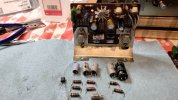
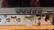
I made it through the tone board after a lot of bad thoughts pertaining to the soldering and the bending of leads flat to the board. Glad this is not the standard on most brands. I forgot to snap pics of the completed board but I will say that it looks better, a lot better now and the snaps and pops are gone! I replaced all the missing button labels and they look fantastic! I have completed the left amp board and the amount of current drawn is quite noticable just from my DBT. I have pictures this time though.
 

Attachments

  • IMG20230927181931.jpg
    IMG20230927181931.jpg
    110.2 KB · Views: 28
  • IMG20230927181637.jpg
    IMG20230927181637.jpg
    78.1 KB · Views: 28
  • IMG20230927181633.jpg
    IMG20230927181633.jpg
    80.4 KB · Views: 29
Once you start the restoration please take pictures and post, either in progress or when done. Unless, of course, the link from @dlucy already says it all, though pictures would still be nice.
Here are more pictures. I have managed to complete the replacement of filter caps
 

Attachments

  • IMG20230928202337[1].jpg
    IMG20230928202337[1].jpg
    120.1 KB · Views: 23
  • IMG20230928202544[1].jpg
    IMG20230928202544[1].jpg
    124.9 KB · Views: 23
  • IMG20230928202400[1].jpg
    IMG20230928202400[1].jpg
    109.5 KB · Views: 23
Here is my lighting wiring and I think that this looks better than what was in this from the factory. That was just a rats mess of wires stuffed in the metal cover.
 

Attachments

  • IMG20230928202923[1].jpg
    IMG20230928202923[1].jpg
    124.1 KB · Views: 22
Well I hit my first brick wall. I went through the power boards F-1317 and recapped it and replaced two carbon resistors with film resistors, installed the board and nothing. No sound, no radio output, no voltages on the board. 83v on the 3300uF cap and 44 on the 2 2200uf caps. The only voltage I am getting on the board is on the yellow wire, 44v. Tomorrow I will pull it out and find out what went wrong. It was making power prior to my recap...so....What did I do.....?
 
Last edited:
Well I hit my first brick wall. I went through the power boards F-1317 and recapped it and replaced two carbon resistors with film resistors, installed the board and nothing. No sound, no radio output, no voltages on the board. 83v on the 3300uF cap and 44 on the 2 2200uf caps. The only voltage I am getting on the board is on the yellow wire, 44v. Tomorrow I will pull it out and find out what went wrong. It was making power prior to my recap...so....What did I do.....?

Most-typical issues:

  1. Bad solder joint or cold solder joint, so just reflow every joint.
  2. Installed a cap or transistor or diode backwards, so just compare current positions (of legs and orientation) to the photos you took of board before changes.
 
I placed the board back in and it did have power but appears that the SCR is blocking the output. I have ordered a new SCR and figured that as long as I have it out I might as well replace the diodes and transistors so I ordered up the rest of the components to bring the board back to reliable standards.
 
Back
Top Bottom