


Hello from Ohio!
I'm at the last leg of restoring this beautiful receiver that sat in storage for over 20 years it's in great condition and has all the button labels, also came with service manual, operation manual, schematic, and warranty card, I’ve never bought something with so much paper work.
Last night was able to set the bias at 30ma for both left and right channel and music was playing great in both channels. Had everything back together except for the wooden cover and faceplate, this morning I installed the faceplate and wooden case, did one final check on the dim bulb and my 60w bulb didn’t dim like normal but stayed bright. So after taking everything back apart, I’ve narrowed down where my problem is coming from, the right driver board. I’ve listed below all the troubleshooting steps that I’ve done but I cannot locate were the problem is, and I’m hoping I can get some good orderly direction from the experts. The tools that I have are, fluke DMM, variac, dim bulb, scope, and signal generator.
Work done so far:
When I first bought this receiver, it was advertised that the right fuse was blowing, and I found that the right output transistors were blown. Both left and right output transistors have been replaced with MJ21194G, after being replaced everything was working great.
I’ve deoxited and lube the switches and pots several times since I’ve read that the switches are notorious for being dirty.
Tone board (this Sansui is the older style with the big tone board), power/protection board (SCR mod NOT done), and driver boards have been rebuilt with new caps and known faulty transistors replaced. After every board was rebuilt, the bias was set for both left and right channel and confirmed music played in Aux (FM is very faint, but AM does work) in both left and right channels with no distortion, pops, cracks, etc., also made sure all knobs and switches didn’t create any new noises of pops and crackles before moving onto the next board. The BOM that I’ve used has been from the two links below:
https://audiokarma.org/forums/index...recap-and-restore.807427/page-5#post-12254758
https://audiokarma.org/forums/index.php?threads/sansui-7000-restore.963684/
Troubleshooting:
Main in and pre amp plugs have been pulled for all troubleshooting steps
Bulb goes dim when both driver boards have been pulled, and only goes bright when the right driver board has been connected.
With only the right driver board and leaving the left disconnected, it does not matter which slot the right driver board is connected into, bulb glows bright and stays bright in either one. But with the right board disconnected and the left connected, the bulb is dim, does not matter which slot the left board is connected too, the bulb is dim.
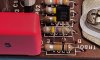
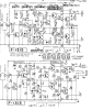
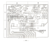
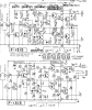
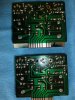
Both driver boards have all new caps, doubled and triple checked for correct polarity, TR801 and TR802 have been replaced with KSC945CG and KSC1845. I’ve included pics of both, I’ve been wrong before on the orentation.
Since the left driver board works, I’ve installed the remaining transistors that have not been replaced from the left board to the right board one at a time to see if the short disappears on the right board but no change. So far i've swapped from the left to the right, TR805, TR806, TR804, and TR803. So it appears that the transistors on the right driver board are good? This is what i'm unsure of and not sure of what steps to take next.
Reflowed all joints, checked for continuity, tested everything for anything that is shorted with compenent still soldered in the board (didn't find anything OL), and as always looking for cracks.
Thank you so much! From the little that i've heard in my test speakers out in the garage, this receiver is going to sound amazing.
I'm at the last leg of restoring this beautiful receiver that sat in storage for over 20 years it's in great condition and has all the button labels, also came with service manual, operation manual, schematic, and warranty card, I’ve never bought something with so much paper work.
Last night was able to set the bias at 30ma for both left and right channel and music was playing great in both channels. Had everything back together except for the wooden cover and faceplate, this morning I installed the faceplate and wooden case, did one final check on the dim bulb and my 60w bulb didn’t dim like normal but stayed bright. So after taking everything back apart, I’ve narrowed down where my problem is coming from, the right driver board. I’ve listed below all the troubleshooting steps that I’ve done but I cannot locate were the problem is, and I’m hoping I can get some good orderly direction from the experts. The tools that I have are, fluke DMM, variac, dim bulb, scope, and signal generator.
Work done so far:
When I first bought this receiver, it was advertised that the right fuse was blowing, and I found that the right output transistors were blown. Both left and right output transistors have been replaced with MJ21194G, after being replaced everything was working great.
I’ve deoxited and lube the switches and pots several times since I’ve read that the switches are notorious for being dirty.
Tone board (this Sansui is the older style with the big tone board), power/protection board (SCR mod NOT done), and driver boards have been rebuilt with new caps and known faulty transistors replaced. After every board was rebuilt, the bias was set for both left and right channel and confirmed music played in Aux (FM is very faint, but AM does work) in both left and right channels with no distortion, pops, cracks, etc., also made sure all knobs and switches didn’t create any new noises of pops and crackles before moving onto the next board. The BOM that I’ve used has been from the two links below:
https://audiokarma.org/forums/index...recap-and-restore.807427/page-5#post-12254758
https://audiokarma.org/forums/index.php?threads/sansui-7000-restore.963684/
Troubleshooting:
Main in and pre amp plugs have been pulled for all troubleshooting steps
Bulb goes dim when both driver boards have been pulled, and only goes bright when the right driver board has been connected.
With only the right driver board and leaving the left disconnected, it does not matter which slot the right driver board is connected into, bulb glows bright and stays bright in either one. But with the right board disconnected and the left connected, the bulb is dim, does not matter which slot the left board is connected too, the bulb is dim.
Both driver boards have all new caps, doubled and triple checked for correct polarity, TR801 and TR802 have been replaced with KSC945CG and KSC1845. I’ve included pics of both, I’ve been wrong before on the orentation.
Since the left driver board works, I’ve installed the remaining transistors that have not been replaced from the left board to the right board one at a time to see if the short disappears on the right board but no change. So far i've swapped from the left to the right, TR805, TR806, TR804, and TR803. So it appears that the transistors on the right driver board are good? This is what i'm unsure of and not sure of what steps to take next.
Reflowed all joints, checked for continuity, tested everything for anything that is shorted with compenent still soldered in the board (didn't find anything OL), and as always looking for cracks.
Thank you so much! From the little that i've heard in my test speakers out in the garage, this receiver is going to sound amazing.
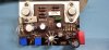
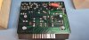
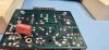
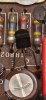



 , I’m not sure what the problem is but it appears that it’s fixed but tomorrow I will do more test and since I have all brand new transistors on the left board I will do the same for the right so they match.
 Regarding the SCR mod, I was unsure of which cables to disconnect, from what I’ve read the wording, to me, appeared to be vague, but I will disconnect those two wires to make sure there are no future problems.