buerwi01
New Member
Hi everyone,
I’m a long time lurker, first time poster, so thank you in advance for any assistance you can offer!
I have an issue where the left channel on my Sansui 7070 stopped working, and was momentarily fixed by cycling the switches. However, it then stopped working again, and when I took a look at the driver board I could see that the main fuses (F02 an F03) were blown. I replaced them with a few 7a 250v fuses (I see they are marked for 125v, but was of the impression 250v should work fine since that’s the maximum voltage), but they also blew out as soon as I turned it on.
I checked the fuse resistors on F-2624 that seem to cause people problems (R33 & 34, and R41-44), but they all seemed to be working fine. Furthermore, I tried removing F-2624 entirely and replacing the blown fuses with new ones, only to have them blow out as well.
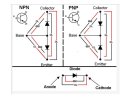
I’ve been combing through posts on this thread and see that the likely culprit is now the output transistors. Can anyone confirm whether this is what I should be checking next, and if so how I can determine whether they are functioning properly or need to be replaced? I would prefer to fix it myself, as I have been enjoying learning how it works. And I’m still very new to this and understand if I’m now in over my head.
I’m a long time lurker, first time poster, so thank you in advance for any assistance you can offer!
I have an issue where the left channel on my Sansui 7070 stopped working, and was momentarily fixed by cycling the switches. However, it then stopped working again, and when I took a look at the driver board I could see that the main fuses (F02 an F03) were blown. I replaced them with a few 7a 250v fuses (I see they are marked for 125v, but was of the impression 250v should work fine since that’s the maximum voltage), but they also blew out as soon as I turned it on.
I checked the fuse resistors on F-2624 that seem to cause people problems (R33 & 34, and R41-44), but they all seemed to be working fine. Furthermore, I tried removing F-2624 entirely and replacing the blown fuses with new ones, only to have them blow out as well.
I’ve been combing through posts on this thread and see that the likely culprit is now the output transistors. Can anyone confirm whether this is what I should be checking next, and if so how I can determine whether they are functioning properly or need to be replaced? I would prefer to fix it myself, as I have been enjoying learning how it works. And I’m still very new to this and understand if I’m now in over my head.