• The move to the new server is done. There are some software and database maintenance updates in process. This has us passing the hat around to help out. We appreciate any donations. Seriously, even a dollar helps. The payment page may be found here - https://www.audiokarma.org/support.html

Sansui 771 Clean-up

I was able to get back to this yesterday. I reflowed the TR06 pins, but did not get any change to the previous results and went ahead and desoldered and removed TR06 which is a 2SD330 NPN. With that removed I checked it with my DMM in diode mode based on a test method I found on-line:

+to base, - to collector = .6 - .7 Vdc, actual .595 vdc
+ to base, - to emitter = .6 - .7 Vdc, actual .694

- to base, + to collector = 0Vdc, actual "OL"
- to base, + to emitter = 0Vdc, actual "OL"

So if I'm doing this right and as mrk229 expected the TR06 2SD330 is bad. From checking other posts it sound like the TP41 is a good replacement that may be useful for other applications.
Actually that looks like the transistor is OK. You should test it one more way.

Check collector to emitter swapping the + and - leads as you did before.
That makes it a six way test. it should be 0 or "OL" both ways.
 
I ran the 3rd test and
- to collector, + to emitter = "OL"
+ to collector, - to emitter = "OL"

Then I rechecked the first tests
+ to base, - to collector = .595 or very close, always about the same
+ to base, - to emitter starts out at 1.2 or so, then settles in a few seconds to .62 to .64. I did this a few times and for several tries I was just getting "OL"

Could it be that with in circuit conditions this NPN will be failed open at the emitter?
.
 
I ran the 3rd test and
- to collector, + to emitter = "OL"
+ to collector, - to emitter = "OL"

Then I rechecked the first tests
+ to base, - to collector = .595 or very close, always about the same
+ to base, - to emitter starts out at 1.2 or so, then settles in a few seconds to .62 to .64. I did this a few times and for several tries I was just getting "OL"

Could it be that with in circuit conditions this NPN will be failed open at the emitter?
.
That B to E reading is not good, the voltage drop should be stable just like the B to C reading. Unless your meter is not making a really good connection to the emitter lead, those B to E readings say to me replace it.
 
Been busy decking the halls, but got some TP41's Mouser for the TR06. The first one a pulled out of the package spec'd out OK so I installed it. I did not get 13.6 Vdc at the TP 26, but my soldering may be suspect. I'll check it out some more this weekend. More deking the halls to do.
 
Finally getting back to work on this. I replaced TR06 with the TP41, but did not get 13.6 V at TP26. I didn't like the looks of my soldering for TR06 so I removed it, checked the B, C, E per the previous test, all good, so I reinstalled. Still not getting 13.6 V. B = 46 V as before, but C = 51mV and E = 40 mV. Also, ZD01 which was 13.6 V before I did anything is now 1V on the collector side and 21 mV on the ground side. Hope I didn't make things worse. On the good side I am getting 32.95 V at TP 25, so that adjacent part of the pwr brd is apparently OK. I'm checking other nearby voltages and will post results later today or tomorrow.
 
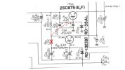
Here are some voltages I was able to take from the circuit around TR06. I see that R04 on the schematic does not exist on the PCB, but on the trace side is a jumper over to I think the base of TR05.
 

Attachments

  • Pwr Brd TR06 Area.jpg
    Pwr Brd TR06 Area.jpg
    42.9 KB · Views: 9
Back
Top Bottom