• The move to the new server is done. There are some software and database maintenance updates in process. This has us passing the hat around to help out. We appreciate any donations. Seriously, even a dollar helps. The payment page may be found here - https://www.audiokarma.org/support.html

Sansui 790 low/no left output

EWorld

Member
Recently started working on a Sansui 790, audio on left was low. Bias checked ok at this time.

I read a forum here on the Sansui 7070 (similar model), and checked for breaks in the solder joints and the traces, resoldered just to be safe, no change.

Pulled and cleaned the relay, no change.

Now the relay will not engage if the F-2624 board is installed.

Found a rebuild kit on ebay from Ben, I replaced all the parts carefully checking orientation, checked output transistors as well, unit will still not engage the relay while the F-2624 driver board is in place.

All fuses are good.

Any suggestions on where to go from here?

Thank you
Ryan
 
Register to hide this ad
What did you rebuild? You need to check the DC offset at a point before the protection relay. Near the relay there should be two coils of copper wire. There will be a resistor in parallel with each of them. They should be identified as R21 and R22. Measure the DC voltage between each of those resistor and chassis ground. If you are lucky, you may only need to adjust the DC offset.

- Pete
 
What did you rebuild? You need to check the DC offset at a point before the protection relay. Near the relay there should be two coils of copper wire. There will be a resistor in parallel with each of them. They should be identified as R21 and R22. Measure the DC voltage between each of those resistor and chassis ground. If you are lucky, you may only need to adjust the DC offset.

- Pete
I should have clarified, I purchased a rebuild kit for the F-2624 board. I will check the DC offset, thank you.
 
What did you rebuild? You need to check the DC offset at a point before the protection relay. Near the relay there should be two coils of copper wire. There will be a resistor in parallel with each of them. They should be identified as R21 and R22. Measure the DC voltage between each of those resistor and chassis ground. If you are lucky, you may only need to adjust the DC offset.

- Pete
With the boards all in place there is -6v on R21 and R22.

When I remove the F-2624 board that drops to zero and the relay engages.
 
6V on those resistors is your problem. It should be close to zero. I don't think the DC offset trimmers on the F-2624 board will have enough range to bring the offset back to zero but give it a try. The service manual will show you which trimmers are for offset and which are for bias. Have you tried setting either of these values?

If you can't adjust it into range, you need to check your work on the F-2624 board. Make sure everything is installed correctly and there are no solder bridges. The schematic will give you voltage values at various points on the board. Start checking. Also, if you aren't using a dim bulb tester, build one and start using it before you start burning up components.

- Pete
 
6V on those resistors is your problem. It should be close to zero. I don't think the DC offset trimmers on the F-2624 board will have enough range to bring the offset back to zero but give it a try. The service manual will show you which trimmers are for offset and which are for bias. Have you tried setting either of these values?

If you can't adjust it into range, you need to check your work on the F-2624 board. Make sure everything is installed correctly and there are no solder bridges. The schematic will give you voltage values at various points on the board. Start checking. Also, if you aren't using a dim bulb tester, build one and start using it before you start burning up components.

- Pete
Adjusting the offset does change it but not by much, I cant find a schematic that has the voltages that are not blacked out. I triple checked the F-2624 board, all parts look like they are installed correctly and I do not see any bridged connections. Would you happen to have a schematic with the voltages for that board?
 
There's a good schematic for the 7070/790 on the Sansui pages of the Digital Docs forum. Concentrate on the negative rail side of the driver board schematic. Since both channels are giving the same reading, also look at the negative power supply on the power supply board.

The same driver board, F-2624, is used in the 9090DB, 8080DB and the black trimmed variants 990DB and 890DB. It's likely someone has already solved this issue. Use the forum search feature and start reading.

- Pete
 
There's a good schematic for the 7070/790 on the Sansui pages of the Digital Docs forum. Concentrate on the negative rail side of the driver board schematic. Since both channels are giving the same reading, also look at the negative power supply on the power supply board.

The same driver board, F-2624, is used in the 9090DB, 8080DB and the black trimmed variants 990DB and 890DB. It's likely someone has already solved this issue. Use the forum search feature and start reading.

- Pete
Ok after going through the power supply i found a bridged connection on one resistor (R04) replaced it as it was original, now it turns on, on DBT biased and tested.

Left channel is Low volume but everything works otherwise. Any ideas why the level difference, I cleaned the controls.
 
Just because you cleaned the controls doesn't guarantee they are clean. Dirty controls is by far the most common cause of channel dropout. "Exercise" all the controls on the front panel. Do any of them cause any change to sound quality? Press the mono switch. Do you get good sound from both channels? If so, the signal path after the mono switch is good and your dropout is occurring before the mono switch.

- Pete
 
Just because you cleaned the controls doesn't guarantee they are clean. Dirty controls is by far the most common cause of channel dropout. "Exercise" all the controls on the front panel. Do any of them cause any change to sound quality? Press the mono switch. Do you get good sound from both channels? If so, the signal path after the mono switch is good and your dropout is occurring before the mono switch.

- Pete
No change in sound quality when working any control, Mono switch makes no difference. It seems like the right channel is very high compared to left, when I turn the volume up with the balanced centered the unit clips and the relay disengages before I get to the first mark on the chassis, sound is clear and clean the whole time.

If I turn the balance to the left all the way I can turn it up normally and no clipping. So I'm not sure if I have over amplification on the right or low amplification on the left.
 
If the mono switch doesn’t change anything, the problem is after the switch. It shouldn’t go into protection. Hard to tell what’s going on without a ‘scope.

Clipping shouldn’t trigger protection. Look for high DC voltage on the output.

- Pete
 
If the mono switch doesn’t change anything, the problem is after the switch. It shouldn’t go into protection. Hard to tell what’s going on without a ‘scope.

Clipping shouldn’t trigger protection. Look for high DC voltage on the output.

- Pete
I can get an O'scope on it, the voltage on the speaker outputs is 0.02v peak.

That made me check the voltage at the outputs themselves, I only have +/- 28v, I think there may be a supply issue.

Further tracing on resistor R04 I have -33v should be -53v. on R30 I have -28v on one side and +28v on the other, should be -44v and +44v

Looks like I am not getting full power for some reason, but the right channel is loud and clear, the left is very low but clear as well.
 
Sorry for the delayed response. Best to get the low voltage sorted out before going any further. It can be caused by one or more resistors drifting out of spec or by a solder bridge or other short drawing the voltage down. Is anything getting hot? Take another look at your soldering to see if there are other solder bridges.

- Pete
 
Sorry for the delayed response. Best to get the low voltage sorted out before going any further. It can be caused by one or more resistors drifting out of spec or by a solder bridge or other short drawing the voltage down. Is anything getting hot? Take another look at your soldering to see if there are other solder bridges.

- Pete
Thank you, I was away so I appreciate the info.

I Have restored power (couple of resistors needed replacing), with the F-2624 driver board removed all is good, with the board in place the relay will not engage, I have not found any shorts or open parts on the board.
 
Go back to post #2 in this thread. With the driver board installed, what are the voltages on those resistors?

- Pete
 
Go back to post #2 in this thread. With the driver board installed, what are the voltages on those resistors?

- Pete

R21 has -2.9v
R22 has -3v

Bias adjust does change them but not enough, looking over the board again to see if i missed a bridged connection somewhere.
 
That's still your problem. Those voltages should be near zero. Anything much higher will trigger protection. Since both channels are about the same it's likely there is a common cause so take another look at the negative side of power supply board. The way the schematic is set up, it doesn't show the wires running between boards. Instead it lists numbers in circles. What are the voltages at #20 (pin 42/45) and #33 (pin 47)? It may be easier to find R04 and R30. If you probe these resistors, you need to pay attention to which side you are measuring. Unlike R21/22 these resistors won't have the same voltage value on both sides.

- Pete
 
That's still your problem. Those voltages should be near zero. Anything much higher will trigger protection. Since both channels are about the same it's likely there is a common cause so take another look at the negative side of power supply board. The way the schematic is set up, it doesn't show the wires running between boards. Instead it lists numbers in circles. What are the voltages at #20 (pin 42/45) and #33 (pin 47)? It may be easier to find R04 and R30. If you probe these resistors, you need to pay attention to which side you are measuring. Unlike R21/22 these resistors won't have the same voltage value on both sides.

- Pete

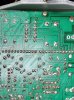
With the board in place.
Pin 42/45 has -45v
Pin 40,41/46,47 -40v
Not sure if you can read the voltages on all the pins.
20220615_155741.jpg
 
Last edited:
I can't read the values written on that image. Both values are low. Do you have it on a dim bulb tester? It would lower the voltage. If not check the values of the related resistors. They may have drifted. The schematic shows voltage values at critical points. Take a look at the rest of them on the negative side.

- Pete
 
Back
Top Bottom