OriginalFlow
New Member
Hey AK,
I've been a happy owner of my Sansui 800 for a few years, thanks to some of the outstanding reviews on this great site!
I have been tinkering on my 800 for most of my ownership and I've been super happy with it.
Searching the archives, nobody has made a post about doing a Baxandall Diode Mod to the 800. Having a AU-555a that I rebuilt, taking inspiration from Leestereo's rebuild thread, I knew what impression the Baxandall Diode can make on quasi-complimentary amps!
Also taking some insight from Conrad Hoffman's webpage I went to work on figuring out a Baxandall Diode Mod on my 800.
I will be the first to admit I've only been doing this tech stuff for a couple years and still learning a ton everyday so I am happy to be corrected by anyone who knows more than I!
What you will need to complete:
1N4xxx diode
220Ω resistor
500Ω trimmer for bias
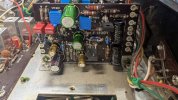
You want to replace r831,r832 on both boards which is a 33Ω resistor. Remove this resistor.
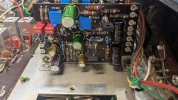
Solder your 220Ω resistor and 1N4xxx diode(I used 1N4007 I have in stock) together and I like to use the diode pins to insert as they're larger. Ensure the cathode(band) is facing the emitter of TR807,808 like in the picture.
Replace vr803 with your 500Ω trimmer, replaces 200Ω trimmer. The stock trimmer is large, so you will need to solder longer pins except the wiper to fit. With many turns you can start to get your bias to increase and set solid at 10v-12mv. You can measure off of 8F with your meter and to ground to set the bias.
I also wanted to add 1% MF resistors to the negative feedback circuit. I am assuming I was correct in identifying r805,r817 as the negative feedback? Open to feedback on that as I'm still learning amp layouts.
*As always, ensure you have a dim bulb on hand when doing work like this*
Listening impressions are very good and it definitely seemed to open the upper-midrange up while keeping it's solid low end. Definitely recommend this to anyone who has a 800!
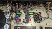
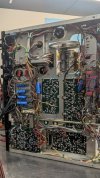
Also adding some pictures of the rest of my unit to peruse.
Thanks for checking this out.
Spence
I've been a happy owner of my Sansui 800 for a few years, thanks to some of the outstanding reviews on this great site!
I have been tinkering on my 800 for most of my ownership and I've been super happy with it.
Searching the archives, nobody has made a post about doing a Baxandall Diode Mod to the 800. Having a AU-555a that I rebuilt, taking inspiration from Leestereo's rebuild thread, I knew what impression the Baxandall Diode can make on quasi-complimentary amps!
Also taking some insight from Conrad Hoffman's webpage I went to work on figuring out a Baxandall Diode Mod on my 800.
I will be the first to admit I've only been doing this tech stuff for a couple years and still learning a ton everyday so I am happy to be corrected by anyone who knows more than I!
What you will need to complete:
1N4xxx diode
220Ω resistor
500Ω trimmer for bias
You want to replace r831,r832 on both boards which is a 33Ω resistor. Remove this resistor.
Solder your 220Ω resistor and 1N4xxx diode(I used 1N4007 I have in stock) together and I like to use the diode pins to insert as they're larger. Ensure the cathode(band) is facing the emitter of TR807,808 like in the picture.
Replace vr803 with your 500Ω trimmer, replaces 200Ω trimmer. The stock trimmer is large, so you will need to solder longer pins except the wiper to fit. With many turns you can start to get your bias to increase and set solid at 10v-12mv. You can measure off of 8F with your meter and to ground to set the bias.
I also wanted to add 1% MF resistors to the negative feedback circuit. I am assuming I was correct in identifying r805,r817 as the negative feedback? Open to feedback on that as I'm still learning amp layouts.
*As always, ensure you have a dim bulb on hand when doing work like this*
Listening impressions are very good and it definitely seemed to open the upper-midrange up while keeping it's solid low end. Definitely recommend this to anyone who has a 800!
Also adding some pictures of the rest of my unit to peruse.
Thanks for checking this out.
Spence