• The move to the new server is done. There are some software and database maintenance updates in process. This has us passing the hat around to help out. We appreciate any donations. Seriously, even a dollar helps. The payment page may be found here - https://www.audiokarma.org/support.html

Sansui 8080

czgeddes

New Member
Hello all of the Sansui enthusiasts! I recently acquired an 8080 (non-DB) and in FM mono both speakers work. In FM Stereo the left channel is out. The same issue occurs in AUX when the stereo/mono mode switch is toggled. The sound is excellent and the unit is completely original.

I’m going to restore it and have done a few restorations recently so I’m comfortable replacing caps, trannies etc… however I’m still a newbie.

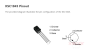
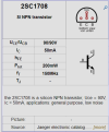
Reading through the various threads all things Sansui 8080’s at issue are the transistors 2sc1708 on the driver board and the discussed replacement for these is the KSC1845. I have these in the FTA configuration and replaced one transistor, put the board back in place.. turned it on and it won’t come out of protection mode.


The pinout for the 2sc1708 is ECB and the KSC1845 is EBC. I swapped the emitter and base.. something I’ve done before but still not comfortable with.

What else? Any advise is welcomed
 
Register to hide this ad
The transistors have been replaced and the intermittent left channel loss remained. I was able to track it down to a bad solder joint on board F-2541. A lucky find really.

I’m moving forward with the restoration and curious just how far to go with it beyond replacing caps, possibly upgrading the main caps to 10,000uf (I’ve seen this in various threads) and the majority of transistors.

For example the AM/FM board F-2549 is original and how far should one go to restoring the original sound? Carbon comp resistors of this vintage can drift and to what degree should these be replaced etc… ceramic caps replaced..

All advice is appreciated.
 
When I get in a legacy audio unit the first thing I do is to check the power supply board F-2546. Get the schematics/Service manual and establish if the power supply board is putting out the correct voltages to the other boards. The schematic gives these numbers. IF THE VOLTAGES ARE NOT WHAT THEY ARE SUPPOSED TO BE THIS HAS TO BE FIXED. Voltage measurements/checks on other pcbs are meaningless if the input voltages are up to specs. Another thing to check is the AC voltage setting on the back of the unit. Make sure it is set to 120 [Not 110]. Next you should think about a DIM bulb tester. Many discussions about this device on Audiokarma. <=An inexpensive but vital tool to keep your 8080 from having a bad day especially after changes.

The F-2541 pcb and it's two resident selector switches controls all line level input and routing of the inputs to the pre-amp boards. The audio from the pre-amp section then is routed back to F-2541 and then routes it to the power amp. The phono amp is also on this board. This board in my experience is the source of signal dropouts in 95% of the time. On the board switch 01 and 02 are the major offenders. Good catch on the bad solder pad. Use a contact cleaner on the switches. Do not disassemble the switch unless you are desperate! These switches are almost impossible to source and expensive if you find one.

On F-2549 pcb. That is a very crowded board. Replacing the carbon comp resistors [I don't think there are many] is in theory a good move. The downside of that is there may not be enough benefit to justify the effort/risk. If the tuner is working I would not dig into the carbon comp resistors. Replacing the capacitors is something I would do and if you are careful you run little risk of doing harm (alignment adjustments). There are two tantalum caps I usually change to films but that is also optional. Changing components on this board may alter alignment so evaluate your tuner before an preemptive moves based on theory/opinion/urban legend,etc.

F-2549 get it's power from F2431[Power Supply Circuit Board] is a board that there is a lot of discussion on by the forum. It is a board that experiences heat stress issues. There are some nice fixes for this issue is discussed on the forum. The contributing issue to the heat stress is the fact Sansui is taking a 36V source and knocking it down to 13V for the F-2549 with two large cermet resistors (3W) and a voltage regulator [which also gets very hot]. Look into this modification. When that is resolved make sure your tuner board is getting 13V (+/-1V) at point 18 and 8V(+/-1v) at point 24 on F-2549. Your tuner will be happier with good voltages.

Note on resistors. I have tested most or all of the OEM carbon film resistors on past Sansui repair projects. These old (and ugly) resistors rarely are out of spec! They are often closer to the specified/indicated value that new stuff. Unless you think your voltages or signal are compromised I leave them alone. If you have a burnt or blown out resistor that needs to be resolved. Resistors make poor fuses and get red hot before they blow leaving a burnt spot on the pcb sometimes. If you see a brand new resistor on a burnt spot on the pcb you will know this board has been "repaired".

Don't let my narrative spook you. The 8080/9090 is a great unit when all fixed up. It is a good unit to learn on as it is all discrete components save the BA312's and the schematic is pretty good. Search Audiokarma and all the known issues are discussed.
 
When I get in a legacy audio unit the first thing I do is to check the power supply board F-2546. Get the schematics/Service manual and establish if the power supply board is putting out the correct voltages to the other boards. The schematic gives these numbers. IF THE VOLTAGES ARE NOT WHAT THEY ARE SUPPOSED TO BE THIS HAS TO BE FIXED. Voltage measurements/checks on other pcbs are meaningless if the input voltages are up to specs. Another thing to check is the AC voltage setting on the back of the unit. Make sure it is set to 120 [Not 110]. Next you should think about a DIM bulb tester. Many discussions about this device on Audiokarma. <=An inexpensive but vital tool to keep your 8080 from having a bad day especially after changes.

The F-2541 pcb and it's two resident selector switches controls all line level input and routing of the inputs to the pre-amp boards. The audio from the pre-amp section then is routed back to F-2541 and then routes it to the power amp. The phono amp is also on this board. This board in my experience is the source of signal dropouts in 95% of the time. On the board switch 01 and 02 are the major offenders. Good catch on the bad solder pad. Use a contact cleaner on the switches. Do not disassemble the switch unless you are desperate! These switches are almost impossible to source and expensive if you find one.

On F-2549 pcb. That is a very crowded board. Replacing the carbon comp resistors [I don't think there are many] is in theory a good move. The downside of that is there may not be enough benefit to justify the effort/risk. If the tuner is working I would not dig into the carbon comp resistors. Replacing the capacitors is something I would do and if you are careful you run little risk of doing harm (alignment adjustments). There are two tantalum caps I usually change to films but that is also optional. Changing components on this board may alter alignment so evaluate your tuner before an preemptive moves based on theory/opinion/urban legend,etc.

F-2549 get it's power from F2431[Power Supply Circuit Board] is a board that there is a lot of discussion on by the forum. It is a board that experiences heat stress issues. There are some nice fixes for this issue is discussed on the forum. The contributing issue to the heat stress is the fact Sansui is taking a 36V source and knocking it down to 13V for the F-2549 with two large cermet resistors (3W) and a voltage regulator [which also gets very hot]. Look into this modification. When that is resolved make sure your tuner board is getting 13V (+/-1V) at point 18 and 8V(+/-1v) at point 24 on F-2549. Your tuner will be happier with good voltages.

Note on resistors. I have tested most or all of the OEM carbon film resistors on past Sansui repair projects. These old (and ugly) resistors rarely are out of spec! They are often closer to the specified/indicated value that new stuff. Unless you think your voltages or signal are compromised I leave them alone. If you have a burnt or blown out resistor that needs to be resolved. Resistors make poor fuses and get red hot before they blow leaving a burnt spot on the pcb sometimes. If you see a brand new resistor on a burnt spot on the pcb you will know this board has been "repaired".

Don't let my narrative spook you. The 8080/9090 is a great unit when all fixed up. It is a good unit to learn on as it is all discrete components save the BA312's and the schematic is pretty good. Search Audiokarma and all the known issues are discussed.
Aldena007,
Thank you for the reply and it's what I needed moving forward. Checking voltages is the next step and the service manual doesn't include a transistor voltages chart. I've done 2 other restorations and the schematics for those hade the voltages for each leg of every transistor. It's something I relied on when troubleshooting and will make one for this unit. I have a DBT, oscilloscope and signal generator....plus the myriad hand tools, soldering items and goopy thermal paste that gets everywhere.

In addition to your advise I'm vaguely aware the 8080's evolved over their manufacturing lifetime and there are mentions of replacing the fusistors etc...regarding the protection circuit on startup plus a few more upgrades. Youtube is a source of info and the channel xraytony made a video on upgrading the driver board. My unit doesn't have any of these. Are schematics or service bulletins available?

Thanks again and I know who to lean on for good advice.
 
There is a significant service bulletin [SSI-0004E] released by Sansui that you should be aware of. These modifications apply to the 8080/9090 units produced before April 1976:!

QUOTE from bulletin:
"THIS MODIFICATION HAS BEEN DONE IN PRODUCTION, FOR 8080 AND 9090 SINCE APRIL 1976. This would preclude serial numbers xx604xxxx and include units thereafter."

I have created a Word version of this document with pictures and annotations. if you want a copy PM me.

NOTE: In my post above the paragraph regarding the power supply there is significant error:

"Voltage measurements/checks on other pcbs are meaningless if the input voltages are up to specs."
Should read:
"Voltage measurements/checks on other pcbs are meaningless if the input voltages are NOT up to specs."

Concerning voltages=> The Sansui 8080/9090 manual is a little sparse when it comes to individual voltages. There is some information scattered around the schematics that cover what I guess Sansui considered important ones.

Save any repair/restoration of F-2436 to the last circuit board to work on. That board won't tolerate mistakes and can take out power transistors and other parts quickly. All startups on this board should always be on DBT. This circuit board is the subject of numerous threads on the forum and a search will turn up excellent information by other members.

Regarding your tool arsenal:

You have a good inventory of tools, but if you don't have a good de-soldering tool get one. The Sansui traces are not very tolerant to excessive heating. Solder braid is the least desirable technique and my recommended tool for this is the handheld vacuum de-soldering tools. There are several on Amazon or online sites.

Feel free to PM me with specific questions on the Sansui 8080/9090, <=my favorite project units.
 
Back
Top Bottom